2-12 | ni.com
Chapter 2 Installation and Configuration
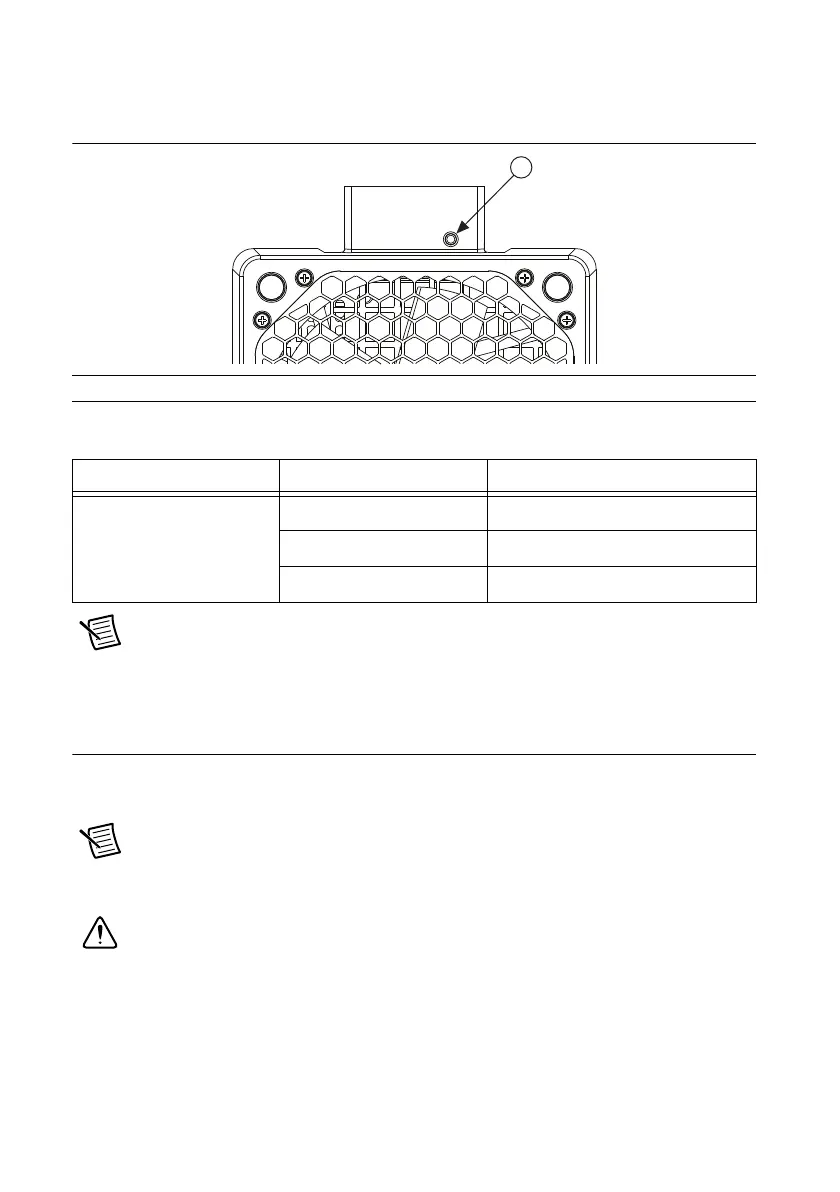
Figure 2-9 shows a fan module LED. Table 2-3 describes the LED states.
Figure 2-9. Fan Module LED
Note If two system fans or both of the power supply fans fail, the chassis shuts
down automatically, preventing the chassis and modules from damage due to
overheating.
Remote Voltage Monitoring and Control
The NI PXIe-1085 Series chassis supports remote voltage monitoring and inhibiting through a
female 8-pin connector on the rear panel. Table 2-4 shows the pinout of the 8-pin connector.
Note The NI PXIe-1085 Series chassis accessory kit includes one 8-pin connector.
To order additional connectors, use Phoenix Contact part number
MC 1.5/8-STF-3.5-BK or 1847181.
Caution The Inhibit/Voltage Mon port can be damaged if subjected to Electrostatic
Discharge (ESD). To prevent damage, industry-standard ESD prevention measures
must be employed during installation, maintenance, and operation.
1 Fan Module LED
Table 2-3. Fan Module LED States
LED State Description
Fan module LED Off Chassis is powered off.
Steady green Fan is operating normally.
Steady red Fan has failed.

 Loading...

