2-10 | ni.com
Chapter 2 Installation and Configuration
Note The Ethernet controller can perform automatic crossover, thus eliminating the
need for crossover cables.
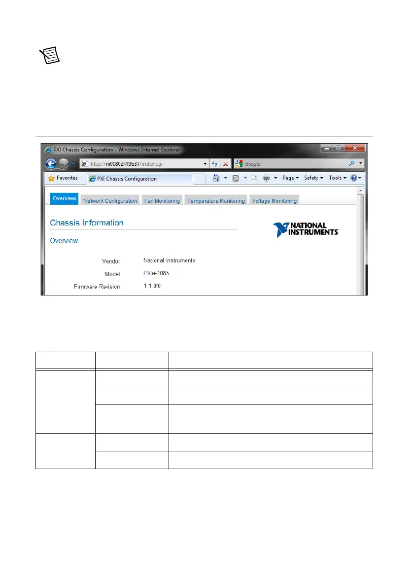
Through the remote monitoring Ethernet interface of the chassis, you can access a web page with
information about the current chassis operating parameters. You can access this page in most
browsers. Enter the IP address or hostname currently assigned to the chassis into the browser’s
address bar. Figure 2-7 shows an example of the web page.
Figure 2-7. Chassis Configuration Web Page
The Ethernet connector has two LEDs that indicate the current status of the Ethernet link.
Table 2-1 describes the behavior of these LEDs.
Default Configuration Settings
The chassis ships from the factory with the following default configuration settings:
• DHCP with Auto IP fallback
• Default hostname as printed on the product label
Table 2-1. Ethernet LED Behavior
LED State Description
ACT/Link Off Link is not established.
Steady green Link is established.
Blinking green Chassis is communicating with another device on the
network.
10/100 Off 10 Mbps data rate is selected.
Steady green 100 Mbps data rate is selected

 Loading...

