© National Instruments | 1-3
NI PXIe-1085 Series User Manual
High Reliability
• 0 to 55 °C extended temperature range
• Power supply, temperature, and fan monitoring
• Field replaceable power supply and fans
Multi-Chassis Support
• PXI Express System Timing Slot for tight synchronization across chassis
• Front panel CLK10 I/O connectors
• Switchless CLK10 routing
Optional Features
• Front and rear rack-mount kits
• Replacement power supply
• EMC filler panels
• Slot blockers for improved cooling performance
• Factory installation services
• Replacement fan modules
Chassis Description
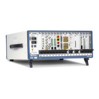
Figures 1-1 and 1-2 show the key features of the NI PXIe-1085 Series chassis front and back
panels. Figure 1-1 shows the front view of the series chassis. Figure 1-2 shows the rear view of
the series chassis.
Note The NI PXIe-1085 24 GB/s chassis can be identified by the blue 24 GB/s
graphic to the left of the 10 MHz REF OUT SMA connector. The NI PXIe-1085
12 GB/s chassis does not have this mark.

 Loading...