1-4 | ni.com
Chapter 1 Getting Started
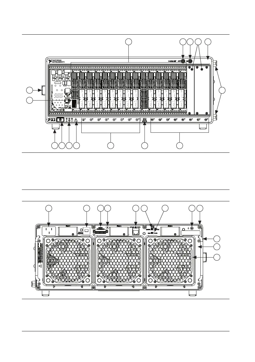
Figure 1-1. Front View of the NI PXIe-1085 Series Chassis
Figure 1-2. Rear View of the NI PXIe-1085 Series Chassis
1 Chassis Carry Handle
2 Backplane Connectors
3 10 MHz REF OUT SMA
4 10 MHz REF IN SMA
5 PXI Filler Panels
6 Chassis Model Name
7 Removable Feet
8 PXI Express Hybrid Peripheral Slots (16x)
9 PXI Express System Timing Slot
10 PXI Express System Controller Slot
11 Temperature, Fan, and Power LEDs
12 Power Inhibit Switch
13 System Controller Expansion Slot
1 Universal AC Input
2 Push-Reset Circuit Breaker
3 Remote Inhibit and Voltage Monitoring Connector
4 Electrostatic-Sensitive Device Symbol
5 Ethernet Port
6 Inhibit Mode Selector Switch
7 Fan Speed Selector Switch
8 Chassis Ground Screw
9 Power Supply Shuttle Mounting Screws (8x)
10 Power Supply Shuttle Handle (2x)
11 Power Supply Shuttle
12 Fan Module (3x)
1
13
5
2
7
8
7
8
9
10
12
11
3
4
6
NI PXIe-1085

 Loading...

