© National Instruments | B-1
B
Pinouts
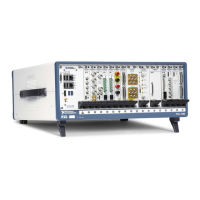
This appendix describes the connector pinouts for the NI PXIe-1085 Series chassis backplane.
Table B-1 shows the XP1 Connector Pinout for the System Controller slot.
Table B-2 shows the XP2 Connector Pinout for the System Controller slot.
Table B-3 shows the XP3 Connector Pinout for the System Controller slot.
Table B-4 shows the XP4 Connector Pinout for the System Controller slot.
Table B-5 shows the TP1 Connector Pinout for the System Controller slot.
Table B-6 shows the TP2 Connector Pinout for the System Timing slot.
Table B-7 shows the XP3 Connector Pinout for the System Timing slot.
Table B-8 shows the XP4 Connector Pinout for the System Timing slot.
Table B-9 shows the P1 Connector Pinout for the peripheral slots.
Table B-10 shows the P2 Connector Pinout for the peripheral slots.
Table B-11 shows the P1 Connector Pinout for the Hybrid peripheral slots.
Table B-12 shows the XP3 Connector Pinout for the Hybrid peripheral slots.
Table B-13 shows the XP4 Connector Pinout for the Hybrid peripheral slots.
For more detailed information, refer to the PXI-5 PXI Express Hardware Specification,
Revision 2.0. Contact the PXI Systems Alliance for a copy of the specification.

 Loading...