Table 2. LED Indicators
LED Description Color Indication
RF 0 RX2 Indicates the receive status of the
device.
Off The device is not active.
Green The device is receiving data.
TX1 RX1 Indicates the transmit status of the
device.
Off The device is not active.
Green The device is receiving data.
Red The device is transmitting
data.
Orange The device is switching
between transmitting and
receiving data.
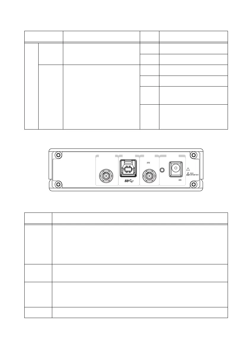
Back Panel
+15 dBm MAX
PPS
5V MAX
USB
PWR
IN
6V
1 A MAX
REF IN
Table 3. Connector Descriptions
Connector Description
REF IN Input terminal for an external reference signal for the local oscillator (LO) on
the device. REF IN is a female SMA connector with an impedance of 50 Ω, and
it is a single-ended reference input. REF IN accepts a 10 MHz signal with a
minimum input power of 0 dBm (0.632 V
pk-pk
) and a maximum input power of
15 dBm (3.56 V
pk-pk
) for a square wave or sine wave.
USB Input that accepts a standard USB cable. A suitable USB cable is included in the
hardware kit.
PPS IN Input terminal for pulse per second (PPS) timing reference. PPS IN is a female
SMA connector with an impedance of 50 Ω, and it is a single-ended input
channel. PPS IN accepts 0 V to 3.3 V TTL and 0 V to 5 V TTL signals.
PWR Input that accepts a 6 V, 3 A external DC power connector.
12 | ni.com | USRP-2900/2901 Getting Started Guide