Table 10. USRP-2943 Module LEDs (Continued)
LED Description Color State Indication
PPS Indicates the pulse per
second (PPS).
OFF — There is no PPS timing
reference signal, or the
device is not locked to the
reference signal.
Green Blinking The device is locked to the
PPS timing reference
signal.
GPS Indicates whether the
GPSDO is locked.
OFF — There is no GPSDO or the
GPSDO is not locked.
Green Solid The GPSDO is locked.
LINK Indicates the status of
the link to a host
computer.
OFF — There is no link to a host
computer.
Green,
yellow, or
red
Solid The host is actively
communicating with the
device.
RF 1 TX1
RX1
Indicates the transmit
status of the module.
OFF — The module is not active.
Red Solid The module is transmitting
data.
Green Solid The module is receiving
data.
RX2 Indicates the receive
status of the module.
OFF — The module is not
receiving.
Green Solid The module is receiving.
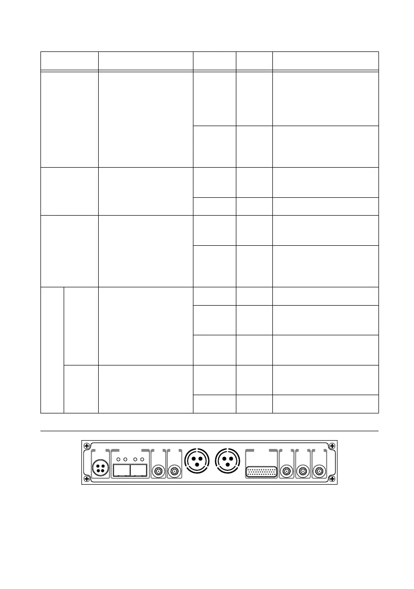
Figure 10. USRP-2943 Module Back Panel
0 1
PWR
REF
IN
PPS
OUT
TRIG
5V DC
REF
OUT
1G/10G ETH
3.3 V +15 dBm
MAX
9-16V DC
7.5 A MAX
SFP+Ports
PCIe x4
TRIG
3.3V
IN
5V MAX
PPS GPS
ANT
–15 dBm
MAX
22 | ni.com | USRP-2940/2942/2943/2944/2945 Getting Started Guide
 Loading...