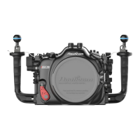
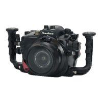
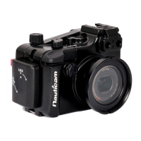
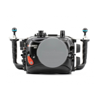
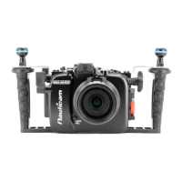
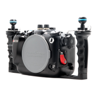
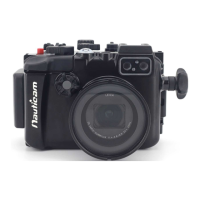
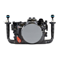
The Nauticam NA-Z8 is an underwater housing designed for the Nikon Z8 camera, identified by product number PN 17229. This user manual provides comprehensive instructions for its use, maintenance, and technical specifications.
Function Description:
The NA-Z8 housing allows the Nikon Z8 camera to be operated underwater, enabling photography and videography in marine environments. It features an integrated LED flash triggering system that fires at the camera's full frames per second (fps), making it suitable for rapid-fire, fast-action shooting. The LED trigger circuit board is mounted directly to the front of the housing and connects to the camera via a hotshoe cable. The housing also incorporates a moisture alarm system to detect leaks, powered by a pre-installed Panasonic CR2032 battery. Various accessory ports and mounting options are available for external strobes, vacuum valves, and other underwater equipment.
Important Technical Specifications:
- Housing Body: Hard Anodized Aluminium Alloy
- Display Window: Abrasion Resistant Polycarbonate
- Dimensions:
- Width: 356 mm
- Height: 204 mm
- Depth: 163 mm
- Weight:
- In air: 3.4 kg
- Buoyancy in water: Negative 0.05 kg (includes camera and battery)
- Depth Rating: 100 m
- Port System: N120 Port System
- Port Accessories: 1 x M24, 2 x M16, 1 x M10, 4 x 1/4-20UNC Threaded Holes
- Integrated Flash Trigger: Manual LED flash trigger (pre-installed)
- Power for Flash Trigger: CR2032 batteries (positive terminal facing up)
- Moisture Alarm Battery: Panasonic CR2032 (pre-installed)
Usage Features:
- Opening and Closing: The housing is opened by depressing the housing unlock button and turning the housing locks outward, then lifting the back housing. Closing involves aligning the front and back housing, ensuring no obstructions, turning the housing locks inward until they click, and ensuring they are securely in place.
- Camera and Lens Installation: The camera tray is attached by tightening a screw into the tripod socket. For Z-mount lenses, ensure the small lever is in a vertical position before installation. For F-mount lenses (with FTZ/FTZ II adaptor), the small lever should be in a horizontal position. If installing with a lens and gear attached, pull out the zoom/focus knob. Ensure the hotshoe plug cable is not obstructed when sliding the camera tray into the housing.
- Port Mounting: Before mounting a port, lubricate the port O-ring. Depress the safety button and rotate anti-clockwise to unlock. Align the index mark and push the port assembly straight in. Rotate the locking lever clockwise to lock.
- Moisture Alarm Setup: Remove the battery insulation film and press the CR2032 battery until it clicks into place. Switch on the alarm; the window will flash blue when working correctly. To test, connect wires with a dampened cotton bud; the alarm will beep and flash red.
- Integrated LED Flash Trigger Setup: Insert CR2032 batteries into holders (positive terminal up). A small LED indicates battery level, turning red when low. Connect the hotshoe plug to the camera's hotshoe. Test by pressing the shutter release button; LEDs under optical bulkheads should flash instantaneously.
- ISO & +/- Value Adjustments: The camera's Custom Settings menu allows "Release button to use dial" (f6) to be set to [ON], enabling ISO and +/- value adjustments by rotating the command dial after the button is released, without removing hands from the handles.
- Optional Vacuum Valve System: Remove the M16 accessory port plug, then remove the cap from the vacuum valve. Lubricate the O-ring and tighten the vacuum valve to the housing. Connect a hand pump to the valve and pump until the target vacuum level is reached. Close the vacuum valve cap. The moisture alarm window indicates vacuum status: Steady Blue (device on), Flashing Blue (standby, ready for pumping), Steady Green (target vacuum reached), Flashing Yellow (vacuum dropping), Flashing Red (vacuum lost/circuit stalled), Alternating Blue and Red (vacuum lost/circuit stalled), Steady Red (out of battery). It is recommended to leave the housing for at least 20 minutes to ensure a seal.
- Strobe Mounting Ball Installation:
- M5 Strobe Mounting Ball (Recommended): Remove the M5 screw using the provided allen key. Screw the #25228 M5 Strobe mounting ball directly onto the M5 thread. An anti-corrosion screw may also be unscrewed during this process.
- M10 Strobe Mounting Ball (Optional): Remove the M5 screw and housing handle screw. Take out the handle and remove the anti-corrosion screw. Replace the handle and screw the M10 strobe mounting ball onto the housing.
- Viewfinder Installation: Remove the pre-installed 0.66x viewfinder by removing its retainer O-ring from inside the rear housing and gently pushing it out. Remove the retainer O-ring from the viewfinder. Align the new viewfinder's alignment pins with the LCD display window and push it into the housing until it cannot go further. Lightly lubricate the retainer O-ring and place it back from inside the housing.
Maintenance Features:
- Post-Dive Care: After salt water usage, soak the housing system in fresh water. Operate all controls and buttons at least three times while immersed in fresh water.
- O-ring Maintenance: Clean and inspect the main O-ring each time after diving for any damage, and every time the housing is opened. Remove the main O-ring using an O-ring remover. Clean the O-ring groove with a cloth, ensuring it is free from salt or foreign materials. Lightly coat the O-ring with the provided lubricant. Return the O-ring by slowly pressing it from one corner to the whole perimeter.
- Storage: Protect the housing with a robust, shock-proof travel case during transportation. Do not travel with the camera inside the housing.
- Servicing: Nauticam recommends shipping the housing to service centers for a complete overhaul after 500 dives or every three years.
Warranty:
All Nauticam Housing Products and Viewfinders are warranted against material and manufacturing defects for two years from the date of purchase for consumer use. Nauticam Optical Accessories carry a one-year warranty, and HDMI cables carry a one-year warranty. This warranty applies only to products purchased from authorized Nauticam dealers and does not extend beyond the original retail purchaser. Service requires contacting regional authorized service centers, and the warranty applies only in the territory where the product was purchased. Nauticam accepts no liability for damage due to improper use, poor maintenance, or to equipment used within its products, nor for loss of captured images due to product malfunction. Unauthorized modifications or repairs invalidate the warranty.