Wiring the radar system | 19
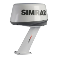
• Remove the shield cover from the underside of the main unit to expose the connector
locations and ground terminal location.
• The broken line shows the route for the interconnection cable.
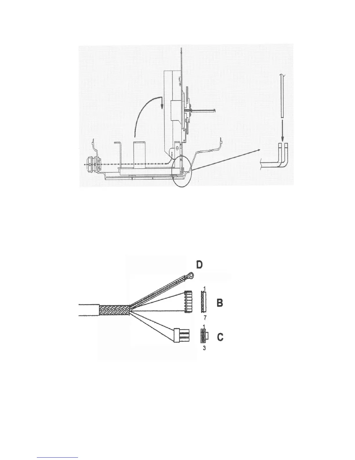
• Identify the connector ends B, C, and D on the 2 kW interconnection cable. Connector D is
a grounding strap.
• Place the locking nut, gasket A and gasket B over the end of the interconnection cable in
the order shown, then push the interconnection cable through the cable entry point into
the radome. (Ensure that you push through sufficient cable to easily join the connectors.)
• At the cable entry point, take care that the grooves in gaskets A and B are opposite each
other (see the figure). Tighten the locking nuts to hold the interconnection cable firmly in
place and to provide a waterproof seal.
 Loading...