EasyManua.ls Logo

Navien NPE-210A User Manual

Navien NPE-210A
103 pages
To Next Page IconTo Next Page
Page #1 background imageLoading...
Page #1 background image
WARNING
If the information in these instructions is not followed exactly, a re or explosion may result, causing
property damage, personal injury or death.
Do not store or use gasoline or other ammable vapors and liquids in the vicinity of this or any other
appliance.
What to do if you smell gas
Ɣ
Do not try to light any appliance.
Ɣ
Do not touch any electrical switch; do not use any phone in your building.
Ɣ
Immediately call your gas supplier from a neighbor’s phone. Follow the gas suppliers instructions.
Ɣ
If you cannot reach your gas supplier, call the re department.
Installation and service must be performed by a qualied installer, service agency or the gas supplier.
The installation must conform with local codes or, in the absence of local codes, the National Fuel Gas Code,
ANSIZ223.1/NFPA 54 and/or CSA B149.1, Natural Gas and Propane Installation Code.
When applicable, the installation must conform with the Manufactured Home Construction and Safety
Standard, Title 24 CFR, Part 3280 and/or CAN/CSA Z240 MH Series, Mobile Homes.
* Lead Free
Keep this manual near this water heater for future reference
whenever maintenance or service is required.
* The wetted surface of this product contacted by consumable
water contains less than one quarter of one percent (0.25%) of
lead by weight.
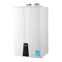
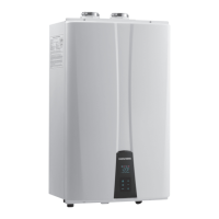
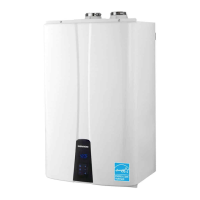
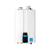
Installation & Operation Manual
NPE Condensing Water Heaters
Model
NPE-180A
NPE-210A
NPE-240A
NPE-150S
NPE-180S
NPE-210S
NPE-240S
CLICK ANYWHERE on THIS PAGE to return to NAVIEN WATER HEATER /
HEATING BOILER AGE & MANUALS at InspectApedia.com

Other manuals for Navien NPE-210A

Questions and Answers:

Navien NPE-210A Specifications

General IconGeneral
TypeTankless
Fuel TypeNatural Gas or Propane
Energy Factor0.97
VentingPVC, CPVC
Water Connection Size3/4" NPT
Gas Connection Size3/4" NPT
Voltage120V
Temperature Range98°F - 140°F
Ignition TypeElectronic
Warranty15 years heat exchanger, 5 years parts
Energy EfficiencyCondensing

Summary

Safety Information

About the Water Heater

Items Included

Lists components found in the water heater box.

Accessories

Lists optional accessories available for the water heater.

Specifications

Details technical specifications for different models, including heat capacity and flow rate.

The Front Panel

Explains the functions of the front panel buttons and displays.

Components

Shows a diagram of the water heater's key internal components.

Dimensions

Provides diagrams and measurements of the water heater, including supply connections.

Rating Plate

Explains the information on the water heater's rating plate and its importance.

Installing the Water Heater

Choosing an Installation Location

Guides on selecting an appropriate installation location, considering clearances, utilities, and drainage.

Mounting the Water Heater to the Wall

Instructions on how to properly mount the water heater to a wall, including safety precautions.

Connecting the Gas Supply

Provides guidelines and safety warnings for connecting the gas supply to the water heater.

Gas Pipe Sizing Tables

Tables showing gas pipe sizing based on length and capacity for natural gas.

Measuring the Inlet Gas Pressure

Explains how to measure inlet gas pressure and the necessary precautions.

Connecting the Water Supply

Details the process of connecting the water supply, including guidelines and filter cleaning.

Using the Water Heater for Combination Water Heating and Space Heating

Guidelines for using the water heater in a combi system for both water and space heating.

Selecting a Recirculation Mode ("A" Model Only)

Explains how to select internal or external recirculation modes for "A" models.

External Pump Wire Connection

Instructions for connecting an external pump's wiring to the water heater's PCB.

Connecting a Pressure Relief Valve

Details the installation of an approved pressure relief valve, including safety warnings.

Connecting the Condensate Drain

Explains how to connect the condensate drain, including disposal options and precautions.

Condensate Neutralizer Kit

Information on the condensate neutralizer kit and its installation.

Venting the Water Heater

Covers the critical aspects of venting, including safety warnings and requirements for Category IV appliances.

Selecting a Vent Type

Discusses direct venting and provides clearance requirements based on installation type and location.

Selecting Vent Pipe Materials

Lists approved vent pipe materials for USA and Canada, with specific cautions.

Measuring Vent Length

Provides tables and guidelines for calculating maximum vent lengths based on pipe size and elbows.

Terminating the Vent

Describes approved vent termination kits and components for PVC and polypropylene materials.

Connecting the Power Supply

Covers electrical connection requirements, safety, and grounding.

Setting the DIP Switches

Explains the purpose and location of DIP switches for configuring the water heater's functions.

Circuit Board DIP Switches

Details the DIP switches on the circuit board that configure model settings.

Setting the Front Panel DIP Switches

Explains how to set DIP switches on the front panel for various configurations like recirculation, altitude, etc.

Installing a Cascade System

Connecting Water Supplies

Provides options for plumbing cascade systems, including internal pump recirculation.

Piping Sizes and Considerations

Discusses pipe diameters and flow rates for cascade systems to prevent erosion.

Connecting the Communication Cables

Explains how to connect Ready-Link communication cables between units in a cascade system.

Configuring the Communication Settings

Details the steps to configure communication settings, setting master and slave units.

Installing a Common Vent System

About the Common Vent System

Introduces the common vent system and its benefits for multiple NPE units.

Guidelines for a Common Vent System

Provides crucial guidelines for safe and correct installation of a common vent system.

Determining the Length of a Common Vent System

Explains how to calculate the required common vent length based on total BTU/H rating and system layout.

Navien Backflow Damper (Back-draft Damper)

Details the Navien backflow damper, its function, and installation requirements for common vent systems.

Starting the Common Vent System

Guides on assembling the backflow damper onto the water heater units.

Backflow Damper Assembly

Step-by-step instructions for assembling the backflow damper.

Connecting the Pipe to the Damper

Instructions for connecting vent pipes to the backflow damper, including safety warnings.

Assembling the T Joint

Details how to assemble the T joint for connecting branch pipes to the common vent system.

Connecting and Terminating the Vent Pipe

Explains how to connect vent pipes to the main trunk and install system terminations.

Connecting the Main Pipe Runs to T Joint

Instructions on connecting main trunk pipes to the tee joints in the common vent system.

Installing the System Termination

Describes how to fit end caps, elbows, or tees at the open ends of vent piping.

Installing a Condensate Drain

Provides examples and instructions for installing a condensate drain hose for the common vent system.

Setting Up the Common Vent System

Guides on setting DIP switches for common vent operation, including altitude settings.

Common Vent Termination Clearances

Specifies clearances for direct vent applications, both vertical and horizontal installations.

Direct Vent Application – Vertical Installation

Illustrates and describes clearances for vertical direct vent termination.

Venting Intake and Exhaust to Different Locations

Shows how intake and exhaust vents can be routed to different locations.

Direct Vent Application – Horizontal Installation

Illustrates and describes clearances for horizontal direct vent termination.

Exhaust Vent Termination Clearances (For Direct Vent)

Provides detailed clearance requirements for direct vent terminations in US and Canada.

Maintenance

Instructions for periodic maintenance of the backflow damper, including checking the damper condition.

Operating the Water Heater

Turning the Water Heater On or Off

Basic instructions on how to power the water heater on and off using the power button.

Adjusting the Water Temperature

Guides on how to adjust the water temperature, including safety warnings about scalding.

Using Commercial Mode

Explains how to enable Commercial Mode for higher temperature settings and its implications.

Viewing Basic Information

How to access and view basic information like flow rate and temperatures on the display.

Setting the Operation Mode

Steps to set the water heater's operation mode (e.g., 1-stage MIN, 2-stage MAX).

Setting the Parameters

Instructions for accessing and modifying special parameters, with strong warnings for professionals.

Pump Exercise Operation Time (P.04)

Sets the time for the pump exercise function to prevent hot water stagnation.

Burn Delay Time (P.05)

Sets the burner delay time for air handler applications to optimize operation.

Pump Post Purge Time (P.06)

Sets the post-purge time after a combustion cycle.

Outdoor Reset Control (P.07–P.10)

Explains how Outdoor Reset Control adjusts heating temperature based on outdoor conditions.

Preheat Pump Output Time (P.12)

Sets the duration for preheating operation or on-demand operation.

Cascade Unit On HC Offset (P.20)

Sets the heat offset value for cascade units when operating.

Cascade Initial Operation Number (P.26)

Sets the initial number of units for cascade operation.

Resetting the Water Heater

Instructions on how to reset the water heater to resolve error messages.

Appendixes

Gas Conversion

Provides detailed instructions and safety warnings for converting the water heater from Natural Gas to Propane Gas.

Technical Data

Presents pressure drop curves for different models of the water heater as a function of water flow rate.

Outlet Flow Data

Displays flow rate charts for various water heater models showing flow vs. temperature rise.

Wiring Diagram

Shows the electrical wiring diagram for the NPE-180A/210A/240A models, including color codes.

Ladder Diagram

Presents the ladder diagram for the NPE-180A/210A/240A models, illustrating control logic.

Component Assembly Diagrams and Parts Lists

Introduces component assembly diagrams and lists the part numbers for various components.

Case Assembly

Shows an exploded view of the water heater's case assembly with numbered parts.

Burner Assembly (NPE-180A/ 210A/ 240A)

Displays an exploded view of the burner assembly for specific NPE models.

Burner Assembly (NPE-150S/180S/ 210S/ 240S)

Shows an exploded view of the burner assembly for different NPE models.

Waterway Assembly (NPE-180A/210A/240A)

Provides an exploded view of the waterway assembly for specific NPE models.

Waterway Assembly (NPE-180S/ 210S/ 240S)

Displays an exploded view of the waterway assembly for different NPE models.

Fan (Gas) Assembly

Shows exploded views of the fan (gas) assembly for various NPE models.

Installation Check list

A comprehensive checklist to ensure all installation steps and requirements have been met.

Navien H2Air Add-on Controller Kit (Optional)

Describes the H2Air controller for combination heating and DHW applications.

Navien HotButton Kit (Optional)

Explains the HotButton kit for efficient DHW recirculation based on actual demand.

Requirements for the State of Massachusetts

Lists specific installation requirements for Massachusetts, including CO detectors and signage.

Getting Service

Related product manuals