14ENGINESYSTEMS
Turbochargers
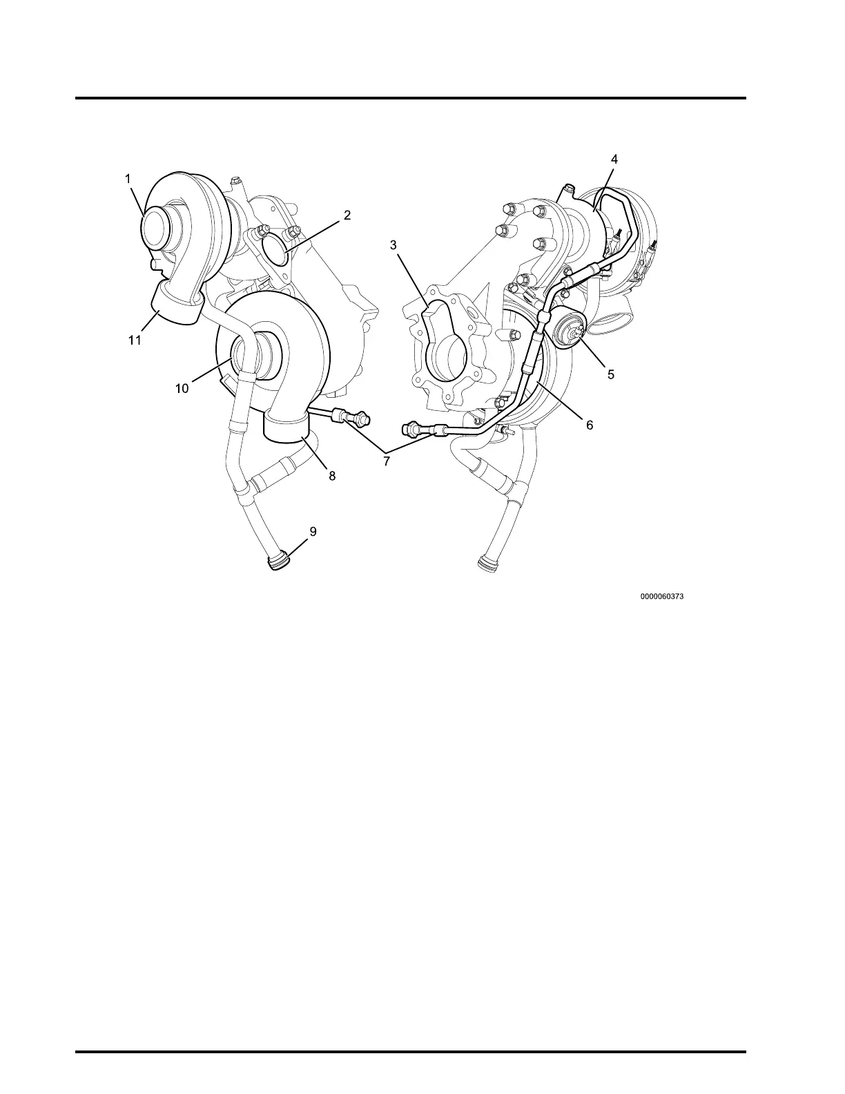
Figure4HighandLowPressureTurbochargerComponents–InnerandOuterviews
1.HighPressure(HP)turbocharger
compressorinlet
2.HPturbochargerturbineinlet
3.LPturbochargerturbineoutlet
4.HPturbocharger
5.HPturbochargerwastegate
actuator
6.LowPressure(LP)turbocharger
7.Turbochargeroilsupplytube
8.LPturbochargercompressor
outlet
9.Oilreturntube
10.LPturbochargercompressor
inlet
11.HPturbochargercompressor
outlet
Navistar
®
N13enginesareequippedwitha
pneumaticallyregulatedtwo-stageturbocharger
system.TheHighPressure(HP)andLowPressure
(LP)turbochargersareinstalledinparallelontheright
sideoftheengine.
Intakeairow:FilteredairenterstheLPcompressor,
whereitiscompressedanddirectedtotheLow
PressureChargeAirCooler(LPCAC).Cooled
compressedairthenenterstheHPcompressor,
whereitisfurthercompressedanddirectedinto
theHighPressureChargeAirCooler(HPCAC).
CompressedairthengoesthroughtheEngine
ThrottleValve(ETV)andtheintakethrottleduct.This
systemprovideshighchargeairpressuretoimprove
engineperformanceandtohelpreduceemissions.
Exhaustgasow:TheHPturbochargeris
connectedtotheexhaustmanifoldthroughtheHP
turbineinlet.ExhaustgasesexittheHPturbine
outletandaredirectedtotheLPturbineinlet.The
HPturbochargerisequippedwithawastegate,
whichiscontrolledbyapneumaticactuator.TheHP
turbochargerwastegateisusedtoregulateboostby
controllingtheamountofexhaustgasthatbypasses
theturbineoftheturbocharger.Whenboostdemand
 Loading...