EasyManua.ls Logo

NCE AR10 - User Manual

NCE AR10
8 pages
Print Icon
To Next Page IconTo Next Page
Loading...
AR10 Auto Reverser
Automatic Reverse Loop Controller
Features of the AR10:
Automatically controls polarity of DCC reverse loops
Provides short circuit protection for loop
Ready to run without any programming
Trip current adjustable 1 to 10 Amps
Easy hookup using screw terminals, no soldering
Solid state design provides silent, reliable operation
Status indication LED
Additional output for remote LED
Automatic or manual reset after short circuit shutdown
Adjustable short circuit response time
This book, schematics and artwork copyright 2020 NCE Corp., Webster, NY 14580
Age
14+
05240233
05240233
Warning: This product contains chemicals known to the state of California to cause
cancer, birth defects or other reproductive harm.
Question and Answer IconNeed help?

Do you have a question about the NCE AR10 and is the answer not in the manual?

Summary

AR10 Automatic Reverse Loop Controller

Key Features of the AR10

Lists key advantages and functionalities of the AR10 device.

Installation and Setup

Description and Mechanical Installation

Details the AR10's purpose, DCC compatibility, and mounting guidelines.

Electrical Connections and Wiring

Explains how to connect the AR10 to the track and DCC system.

Recommended Feeder Spacing

Guidance on track feeder placement for optimal performance.

Trip Current Setting Recommendation

Advice on setting the trip current based on DCC system capacity.

Configuration and Testing

Setting Trip Current Levels

Explains how to adjust the trip current using onboard switches.

Testing the Installation

Describes the 'quarter test' procedure to verify wiring and functionality.

Indicator LEDs and Connections

Understanding Indicator LEDs

Explains the meaning of the SHORT, NORMAL, and REVERSE status LEDs.

AR10 Connections Overview

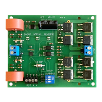
Details connections for DCC power, loop track, remote LEDs, and manual reset.

Switches on the AR10

Identifies the trip current setting switches on the AR10 board.

Advanced Configuration (CVs)

Programming CVs (Optional)

Describes two methods for programming AR10 configuration variables (CVs).

Fine Tuning AR10 Parameters

Details CVs for adjusting short circuit response and shutdown times.

Manual Reset Configuration

Explains how to enable and use the manual reset feature via CV131.

Customization and Reset

Custom Startup Table (CVs)

Explains the custom startup table for pulsing track power before operation.

Factory Reset Procedure

Details how to reset the AR10 to its original factory settings using CV147.

Product Specifications and Warranty

AR10 Technical Specifications

Lists dimensions, input current, voltage, and trip point details.

Device Warranty Information

Outlines the warranty period and conditions for the AR10 device.

Overview

The NCE AR10 Auto Reverser is an automatic reverse loop controller designed for use with DCC (Digital Command Control) systems, specifically for managing track polarity in reverse loops. It ensures seamless operation of trains as they enter and exit reverse loops by automatically adjusting the track polarity, eliminating the need for manual intervention. This device is not compatible with non-DCC power systems.

Function Description

The primary function of the AR10 is to automatically control the polarity of DCC reverse loops. In a reverse loop, a train enters a section of track that eventually reverses its direction relative to the main line. Without polarity control, a short circuit would occur when the train bridges the gap between the main line and the reverse loop due to conflicting polarities. The AR10 detects the train's presence and automatically switches the polarity of the reverse loop track to match the main line, preventing short circuits and allowing continuous operation.

Beyond polarity control, the AR10 also provides short circuit protection for the loop. If a short circuit or overload condition is detected within the reverse loop, the AR10 will remove power to that section of track to prevent damage to the system. It then attempts to restore power periodically until the short circuit is cleared. This protective feature safeguards your DCC system and rolling stock.

The device is designed for ease of use, coming ready to run without requiring any complex programming out of the box. Its solid-state design ensures silent and reliable operation, a significant advantage over mechanical relays that can be noisy and less durable.

Usage Features

The AR10 offers several user-friendly features for installation, configuration, and operation:

  • Automatic Polarity Control: The core feature, it automatically senses the polarity requirements of the reverse loop and switches it as needed, allowing trains to pass through without stopping or manual intervention.
  • Short Circuit Protection: Built-in short circuit detection and power shutdown for the loop protect your layout from electrical damage. The device will attempt to restore power every 2 seconds by default after a short circuit, until the issue is resolved.
  • Adjustable Trip Current: The trip current, which determines the current level at which the AR10 will shut down power due to a short circuit, is adjustable from 1 to 10 Amps. This allows users to tailor the protection level to their specific DCC system and layout requirements. Settings are configured via three physical switches on the device, with options for 1, 2, 3, 4, 5, 6, 7 Amps, and a custom setting. It is recommended to set the trip current to about 75% of the maximum system current.
  • Easy Hookup: The AR10 utilizes screw terminals for all connections, eliminating the need for soldering and simplifying the installation process. It requires only two wires from the main track (DCC power input) and two wires to the reverse loop track (DCC track power output).
  • Status Indication LED: A built-in LED provides visual feedback on the device's status. A red LED indicates a short circuit or overload condition (power removed from the loop). Green LEDs indicate the loop track polarity, distinguishing between "NORMAL" and "REVERSE" states. The red LED also flickers rapidly when the SETUP button is pressed, indicating readiness to accept programming commands.
  • Remote LED Output: An additional output is available for connecting a remote status LED. This allows users to monitor the AR10's status from a more convenient location on their layout, duplicating the actions of the on-board SHORT LED. Current limiting resistors are integrated, so only an LED needs to be connected.
  • Automatic or Manual Reset: After a short circuit shutdown, the AR10 can be configured for either automatic or manual reset. By default, it attempts to restore power automatically. However, users can enable a manual reset feature via CV settings, allowing them to connect an external pushbutton switch to manually recover from a short circuit.
  • Adjustable Short Circuit Response Time: The time delay between the occurrence of a short circuit and the actual power shutdown is adjustable via CV129. The factory default is 16 milliseconds, but it can be lengthened up to 512 milliseconds, allowing users to fine-tune the responsiveness to short circuits.
  • Adjustable Short Circuit Shutdown Time: The duration for which track power remains off after a short circuit is detected is adjustable via CV130. The factory default is 2 seconds, but it can be changed from 16 milliseconds to 4 seconds.
  • Custom Startup Table: For advanced users, the AR10 includes a custom startup table (CV135-CV146) that allows for programmable pulsing of track power on and off multiple times before testing for overcurrent. This can be useful for boosters with weak startup capabilities.
  • Mounting: The AR10 features four mounting holes for secure installation on a layout using #4 x 3/4" round head screws. Care should be taken not to overtighten the screws to avoid damaging the circuit board.
  • Wiring Recommendations: For optimal performance, it is recommended to use #12 AWG wire for terminal strips and track feeder wires every 8-10 feet for code 83 or larger rail, or every 6 feet for code 70 or smaller rail. Insufficient feeders can lead to voltage drop, affecting the circuit breaker's functionality.
  • Testing Installation: A "quarter test" is recommended after installation to verify wiring. By shorting the rails in the reverse loop with a coin, users can confirm that the AR10 trips and shuts down power as expected, then attempts to restore it.

Maintenance Features

While the AR10 is largely a "set and forget" device, it does offer features that facilitate maintenance and troubleshooting:

  • Factory Reset: The device can be reset to its original factory settings by setting CV147 to 85. This is useful for troubleshooting or returning the device to a known good state after extensive configuration changes.
  • CV Programming: The ability to program various CVs (Configuration Variables) allows for fine-tuning of operational parameters. This includes adjusting short circuit response times, shutdown times, and enabling manual reset. CVs can be programmed using either OPs mode programming (Program On the Main) for locomotives or, for NCE systems, OPs mode programming for accessories.
  • Status LEDs: The on-board and optional remote status LEDs provide immediate visual feedback on the AR10's operational state, aiding in quick diagnosis of issues such as short circuits or polarity changes.
  • Robust Design: The solid-state design contributes to the device's reliability and reduces the need for mechanical maintenance typically associated with relays.
  • Clear Documentation: The manual provides detailed instructions for installation, configuration, and troubleshooting, empowering users to maintain and optimize their AR10.

NCE AR10 Specifications

General IconGeneral
ManufacturerNCE
CategoryController
SystemDCC
Input Voltage12-18V DC
ProtectionShort Circuit Protection

Related product manuals