6 of 7
ISSUED: 03-26-10 SHEET #: 125-9106-3 08-04-10
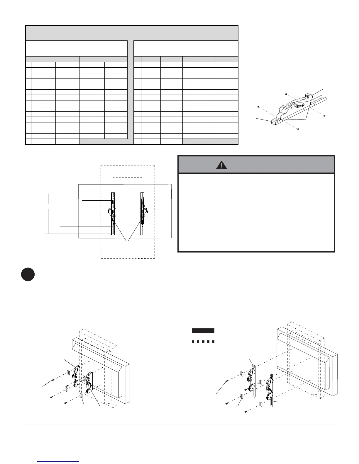
LANDSCAPE PORTRAIT
RecommendedHolePattern RecommendedHolePattern
A 200mmX200mm C 400mmX400mm A 200mmX200mm C 400mmX400mm
B 300mmX300mm D 400mmx200mm B 300mmX300mm D 200mmx400mm
Screen Screw
Size Screen ScrewSize Screen ScrewSize Screen ScrewSize
A ASPV32 M6x12 B P401 M6x12 A ASPV32 M6x12 B P401 M6x12
A ASPV40 M6x12 B P461 M6x12 A ASPV40 M6x12 B P461 M6x12
A E321 M6x12 C P521 M6x12 A E321 M6x12 C P521 M6x12
D E421 M6x12 C P551 M6x12 D E421 M6
x12 C P551 M6x12
D E461 M6x20 B S401 M6x12 D E461 M6x12 B S401 M6x12
A LCD3210 M6x12 B S461 M6x12 A LCD3210 M6x12 B S461 M6x12
A LCD3215 M6x12 C S521 M6x12 A LCD3215 M6x12 C S521 M6x12
D LCD4020 M6x12 A SC40 M6x12 D LCD4020 M6x12 A SC40 M6
x12
D LCD4215 M6x12 A SC46 M6x12 D LCD4215 M6x12 A SC46 M6x12
D LCD4615 M6x12 D V321 M6x12 D LCD4615 M6x12 D V321 M6x12
D LCD4620 M6x12 D V421 M6x12 D LCD4620 M6x12 D V421 M6x12
C LCD5220 M6x12 D V461 M6x12 C LCD5220 M6x12 D V461 M6x
12
D LCD5710 M8x15 B X461HB M6x12 D LCD5710 M8x15 B X461HB M6x12
D M40 M6x12 B X461UN M6x12 D M40 M6x12 B X461UN M6x12
D M46 M6x12 D M46 M6x12
To prevent scratching the screen, set a cloth on a flat, level surface that will support the weight of the screen. Place
screen face side down. If screen has knobs on the back, remove them to allow the tilt brackets to be attached. Place
tilt brackets (B and C) on back of screen as shown in fig. 2.2. Note: Be sure to attach tilt brackets with handles facing
outward as in figure 2.2. Align tilt brackets to screen mounting holes as recommended by chart below. Attach the tilt
brackets to the back of the screen using the appropriate combination of screws, either M6 x 12 mm socket pin screw
(G), M6 x 20 socket pin screw (H) or M8 x 15 mm socket pin screw (J) and multi-washers (I) as shown in figures 2.3
and 2.4. Verify that all holes are properly aligned, and then tighten screws using security allen wrench (F).
2
Installing Tilt Brackets
Use Chart to Determine Orientation and Screws
Portrait
Landscape
USING EXTENTION BRACKETS
USING TILT BRACKETS ONLY
HANDLES
FACE OUT
Secure extension brackets (L) to left
tilt bracket (B) with four M5 x 6 mm
socket pin serrated washer head
screws (K).
Height of tilt brackets may be
adjusted using holes above and
below center mounting location
holes.
NOTE: Repeat using right tilt
bracket (C).
• Tighten screws so adapter brackets are firmly
attached. Do not tighten with excessive force.
Overtightening can cause stress damage to screws,
greatly reducing their holding power and possibly
causing screw heads to become detached. Tighten to
40 in. • lb (4.5 N.M.) maximum torque.
• If screws don't get three complete turns in the screen
inserts or if screws bottom out and bracket is still not
tightly secured, damage may occur to screen or
product may fail.
WARNING
MAX Distance 400 mm
USE TILT BRACKET ONLY
WHEN MOUNTING TO
SCREEN USING 200 X 200
fig 2.4
fig 2.3
fig 2.2
fig 2.1
* Use multi-washers (I) to attach tilt
brackets (B and C) to your screen
when using M6 x 12 mm socket pin
screw (G), M6 x 20 socket pin
screws (H).
M8 screws do not require
multi-washers (I)
G, H
or J
B
C
I*
G, H
or J
I*
B
C
L
K
B
400 mm
200 mm
300 mm
CENTER
MOUNTING
LOCATIONS
 Loading...