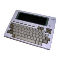
NEC MB Model User's Guide
This guide provides comprehensive information for the NEC MB Model computer, covering its setup, operation, and maintenance. It assumes a basic understanding of Windows operations and the use of help functions within installed applications. The manual specifically refers to Windows® 7 Professional 32-bit with Service Pack 1 (SP1) and emphasizes that system configuration and software installation should be performed by users with administrator privileges.
Checking Included Accessories
Upon unboxing, it's crucial to verify that all included items and accessories are present and undamaged. Any discrepancies should be reported to the place of purchase immediately. The package typically includes:
- Base unit: The main computer chassis.
- Keyboard: For input.
- Two stabilizers: Used to ensure the computer's stability when placed vertically.
- Screw (x1): For securing components.
- Recovery Disc: For system restoration (note: not included with MC32M/B-F and MC33L/B-F models).
- Power cord: To supply power to the computer.
- Mouse: For navigation.
- Cable stopper: To prevent keyboard cable pull-out or protect connected devices from theft.
- Application Disc: For software installation.
- User's Guide: This manual.
- Warranty documents: Including a warranty certificate and service regulations.
- Safety instructions: In various languages.
- Software terms and conditions: For customer review before opening the package.
It's also important to confirm that the model and serial numbers on the base unit match those on the warranty. The written warranty should be kept in a safe place for future reference, as it dictates repair conditions during the warranty period. For post-warranty repairs, contact the place of purchase or a specified customer service location.
Connecting Included Accessories
When connecting any items, avoid touching connector terminals to prevent damage. The LAN cable should only be connected after Windows setup and firewall configuration are complete to ensure secure network connection.
Attaching Stabilizers:
The computer comes with stabilizers for vertical placement. These are not pre-attached. For vertical orientation, one or two stabilizers should be attached to prevent the computer from falling. Stabilizers are not needed for horizontal placement.
- Attaching two stabilizers: Place the computer at the edge of a desk, stabilizing it. Align the stabilizers with the prongs on the computer and slide them until the stopper locks. Exercise caution to avoid finger injury.
- Attaching one stabilizer: If placing the computer vertically with the right front side against a wall, attach one stabilizer to the left front side. Ensure the air vent on the left front side is not blocked. The opposite side of the computer should be placed against the wall for stability.
Connecting Keyboard and Mouse:
Connect the purple keyboard port to the corresponding purple keyboard port. Connect the mouse to a USB port (SS or ).
Connecting the Display:
The display can be connected using either a digital or an analog connector. If using the dual display function on the MB model, connect the display after Windows Setup.
- Digital LCD display: Match the DVI cable icon ( ) and shape to the computer's DVI-D port, then attach and secure with screws.
- Analog LCD display: Match the analog RGB cable icon (☐) and shape to the computer's analog RGB port, then attach and secure with screws.
Connecting Power and Ground Wire:
Insert the power cord plug into an AC wall outlet. Connect the power cord to the computer. If a ground wire is attached to the power cord, connect it to the ground terminal of the AC wall outlet. The power may turn on and off briefly after connection, which is normal.
Windows Setup
Initial power-up requires Windows setup. It's critical to follow the manual's procedure precisely, avoiding skipped steps, pressing unindicated keys, or operating switches, as this can hinder successful setup.
- Avoid external peripherals: Do not connect any peripherals (printers, memory, etc.) other than those specified in the "Connecting Included Accessories" section until Windows setup is complete.
- Avoid LAN cable connection: Connect the LAN cable only after Windows setup and firewall configuration are finalized for secure network connection.
- Do not turn off power: The setup program may appear to pause or show a black screen, but this is normal. Do not interrupt the power during setup.
- Do not leave unattended: Remain with the computer until Windows setup is fully completed, including all key operations and power-off.
Preparation for Setup:
Before starting, decide on a user name and computer name. These should be single-byte alphanumeric characters (20 or less). Avoid double-byte characters, Kana characters, non-standard characters, all symbols, spaces, and restricted strings (CON, PRN, AUX, CLOCK$, NUL, COM1-COM9, LPT1-LPT9, NONE) to prevent setup issues or application malfunctions.
Turning on the Power:
- Turn on the display.
- Press the computer's power switch ( ).
- Never turn off the power during Windows setup. If issues arise or the power switch is accidentally pressed, refer to the troubleshooting section.
Setup Procedure:
- Wait for the [Windows 7 Professional] screen. Set [Country or region], [Time and currency], and [Keyboard layout], then click [Next].
- Enter your user name and computer name, then click [Next].
- A valid user name and computer name are required to proceed.
- Enter a user account password and click [Next].
- Review the [Please read the license terms] page.
- Check [I accept the license terms] and click [Next].
- Setup cannot continue if the license terms are not accepted.
- On the [Help protect your computer and improve Windows automatically] page, select [Use recommended settings], [Install important updates only], or [Ask me later].
- On the [Review your time and date settings] message, set [Time zone], [Date], and [Time], then click [Next]. The screen may change multiple times, and the desktop may take time to appear.
- When the [Shut down your computer] dialog appears, click [OK].
- Click [Start].
- Click [Shut down]. The computer will power off.
- Turn off the display.
- After Windows setup, the computer performs Windows Experience Index measurements during idle periods, which may cause the power plan to change to [High performance] and the display to cut out.
Troubleshooting Setup Problems:
- Accidental power off: This can corrupt system files or the registry. Perform Windows recovery or contact the place of purchase.
- Unresponsive computer or error message: Note the error message, then hold the power switch for at least four seconds for a forced shutdown. Wait at least five seconds before restarting, then refer to the "Accidental power off" instructions.
Using and Configuring After Setup:
Creating Multiple Hard Disk Partitions:
By default, the internal hard disk has one C: drive partition. To create additional partitions:
- Go to [Start] and open [Control Panel].
- Click [System and Security], then [Administrative Tools].
- Double-click [Computer Management].
- In the left pane, click [Storage] → [Disk Management].
- Right-click the (C:) volume.
- Click [Shrink Volume].
- Enter the desired shrink amount in MB.
- Click [Shrink].
- Right-click the unassigned space.
- Click [New Simple Volume].
- Click [Next].
- Enter the desired volume size in MB and click [Next].
- Confirm [Assign the following drive letter:] is selected and click [Next].
- Confirm [Format this volume with the following settings:] is selected and click [Next].
- Click [Finish].
- Do not select [Mark Partition as Active] for the new partition.
- The [Recovery Partition] cannot be shrunk.
- Drive letters can be changed.
- [Shrink Volume] may not be possible in all system environments; refer to the [Computer Management] help file for details.
Creating a System Repair Disc:
It's recommended to create a system repair disc to address issues like corrupted files preventing Windows from loading. Refer to Windows help for instructions.
Windows® Update and Microsoft® Update:
Regularly run Windows® Update or Microsoft® Update to ensure the latest updates are installed.
- Your computer is delivered with all current updates installed. Do not uninstall these updates, as it may reintroduce resolved issues.
Windows Service Pack:
"Windows® 7 Service Pack 1 (SP1)" is pre-installed and cannot be uninstalled.
Knowing the Parts
Front Side Components:
- Optical drive: Built-in DVD Super Multi drive or DVD-ROM drive.
- Power switch ( ): Turns the computer on/off or changes power state.
- Power LED: Indicates power status (green for on, orange for Sleep mode).
- Drive activity LED ( ): Lights when accessing hard disk or optical drive. Avoid pressing the power switch when this LED is lit to prevent damage.
- USB port: Connects to USB devices, supporting USB 2.0 and 1.1. USB 2.0 devices are needed for USB 2.0 transfer speeds.
- Stabilizer: Keeps the computer stable.
Back Side Components:
7. PS/2 mouse port ( ): Connects to a PS/2 (MiniDIN 6-Pin) mouse.
8. PS/2 keyboard port ( ): Connects to a PS/2 (MiniDIN 6-Pin) keyboard.
9. Serial port ( ): Connects to serial devices.
10. Analog RGB port ( ): Connects to an analog interface display.
11. Line input terminal (mini jack) ( ): Inputs audio signals.
12. Mic terminal (mini jack) ( ): Connects microphones and inputs audio signals.
13. Headphone/line out shared output terminal (mini jack) ( ): Outputs audio signals.
14. Air vent: Allows internal heat to escape. Ensure it's not blocked.
15. Cable stopper: Prevents keyboard cable pull-out or protects connected devices from theft. Found in the accessory case.
16. Slide stopper: Fixes the roof cover.
17. LAN port ( ): Connects to a LAN cable.
* Communication speed LED: Orange for 1000 Mbps, green for 100 Mbps, off for 10 Mbps.
* Network communication/Connection LED (ACT/LINK): Flashes during data transfer, or when receiving link pulses from a hub/switch.
18. Chassis lock ( ): Attaches a security cable (sold separately).
19. DVI-D port ( ): Connects to a DVI-D interface display.
20. PCI Express x1 slot: Attaches a PCI Express x1 board, enhancing machine functions.
21. PCI slot: Attaches a PCI board, enhancing machine functions.
22. AC power input jack: Supplies power to the machine via the supplied power cord.
23. USB port (supports USB 3.0) (SS ): Connects to USB devices, supporting USB 3.0, 2.0, and 1.1. USB 3.0 devices are needed for USB 3.0 transfer speeds.
Mouse
A USB mouse is included.
- Sensor operation: The mouse's sensor detects movement using a light source. It may not function properly on reflective surfaces (mirrors, glass), surfaces with continuous patterns (halftone printings), striped surfaces with strong shading, or shiny/transparent/translucent materials.
Using the Scroll Wheel:
Scroll wheel features are available only with supporting applications.
- Vertical scrolling: Rotate the wheel back and forth to scroll up and down.
- Auto scrolling: Click or hold down the wheel to display a scroll icon. Move the mouse in the direction of the arrows to scroll. Click the wheel again or release your finger to make the icon disappear.
LAN Function
This section covers important points and procedures for setting up the Local Area Network (LAN) function.
LAN Settings:
Network connection settings can be changed via [Control Panel] → [Network and Internet] → [View network status and tasks] → [Change adapter settings]. Refer to Windows help for details.
Computer name and network settings can be changed via [Control Panel] → [System and Security] → [System] → [Change settings] under [Computer name, domain, and workgroup settings]. Refer to Windows help for details.
Remote Power On (WoL - Wake on LAN):
WoL allows remote power-on after the computer is off, or remote wake-up from sleep or hibernate. When configured, the LAN adapter remains active even when the computer is off. A special "Magic Packet" transmitted from an administrator's PC triggers the computer to turn on.
- Enabling WoL: Requires special software on the administrator's PC.
- Limitations: WoL cannot be used if the previous system shutdown (power off, sleep, or hibernate) was not completed correctly. Restart Windows and perform a correct shutdown. WoL cannot be used with hubs that only support 1000 Mbps; use a hub that supports 10M/100M/1000M Auto-negotiation.
Configuring WoL (Power Off):
- Turn on power and press repeatedly to enter BIOS setup utility.
- In [Advanced] menu, select [Power Management Setup] and press .
- Set [Resume On LAN] to [Enabled].
- Press .
- Confirm [Yes] and press . Settings are saved, BIOS utility exits, and computer restarts.
Configuring WoL (Sleep/Hibernate):
Settings are found in [Device Manager] → [Network adapters]. Refer to Windows help for details.
Network Booting Function (PXE):
Enables booting via a network and remote connection from an administrator's PC for:
- Operating system installation
- BIOS flashing (rewriting BIOS ROM)
- BIOS configuration changes
Configuring BIOS for Network Booting:
- Turn on power and press repeatedly to enter BIOS setup utility.
- In [Advanced] menu, set [Network Boot Agent] to [Enabled].
- In [Boot] menu, set [1st Boot] to [Network].
- Press .
- Confirm [Yes] and press . Settings are saved, BIOS utility exits, and computer restarts.
Opening and Closing Covers
Removing the Roof Cover:
The roof cover must be removed to install internal devices like memory or PCI boards.
- Caution: The plate can be very hot after use. Wait 30 minutes after turning off the computer and disconnecting the power cord before installing or removing internal devices.
- Turn off the computer.
- Ensure the power LED is off, then remove the power cord and all cables.
- If using a security lock, remove it.
- If the computer is placed horizontally, proceed to step 7. If placed vertically, position it at the edge of a desk for stability.
- Place the computer at the edge of a desk when removing stabilizers to prevent damage.
- Pull the upper stabilizer stopper forward, remove it from the chassis prong, slide the stabilizer in the direction of the arrow, and remove it.
- Be careful not to pinch, strike, or cut fingers when removing stabilizers.
- Release the other stabilizer stopper as described in step 5, slide the stabilizer to the right, and remove it.
- Slide the right and left slide stoppers inward and remove the lock.
- Slide the roof cover to the front and lift it up to remove it where it stops.
Closing the Roof Cover:
- Caution: Hold the cover tightly to avoid pinching, striking, or cutting fingers.
- Attach the roof cover about 40 mm above the back of the machine. Slide the cover to the back, aligning the roof cover hook with the machine's hole.
- Slide the slider stoppers outward and lock the cover.
- If the computer was placed horizontally, proceed to step 6. If placed vertically, position it at the edge of a desk for stability.
- Align the stabilizers with the prongs and slide them until the stopper locks.
- Be careful not to pinch, strike, or cut fingers when attaching stabilizers.
- Stand the computer vertically.
- Attach the security lock, if necessary.
- Connect the power cord and all other cables.
Memory
Before Installing the Board:
Before installing memory, check compatibility, installation order, and slot location. The machine has four memory slots and supports a maximum of 8 GB. Up to four memory cards can be installed (two are factory-installed).
Inserting Memory into the Slot:
Insert memory in the order of DIMM_A2, DIMM_B2, DIMM_A1, and DIMM_B1.
- For dual-channel memory access, install two pairs of same-capacity memory cards in DIMM_A2 and DIMM_B2, or DIMM_A1 and DIMM_B1.
- The maximum memory size is 8 GB, but not all sectors are usable due to space needed for PCI devices. Windows 7 Professional 32-bit allows a maximum of 4 GB.
PCI Board/PCI Express x1 Board
Before Installing the Board:
Available board sizes:
- PCI board: half height (Low Profile), max 64.5 (W) mm × 167.7 (D) mm.
- PCI Express x1 board: Low Profile, max 68.9 (W) mm × 167.7 (D) mm.
Installing:
- Caution: PCI boards are vulnerable to static electricity. Before touching, eliminate static electricity by touching a metal object (e.g., aluminum sash or door knob).
- Do not touch the PCI board port to avoid poor connections or damage.
- Avoid touching parts on the board or solder-mounted areas.
- Do not forcefully insert the PCI board in the wrong direction, as this can damage the connector port or slot.
- Ensure PCI board compatibility.
- Do not touch other internal parts or switches.
- Open the roof cover as described in "Removing the roof cover" (p.10).
- Remove one screw from the PCI board slot cover you are installing, and remove the slot cover.
- Secure the PCI board to the PCI slot using the screw from step 2.
- Close the roof cover as described in "Closing the roof cover" (p.11).
System Configuration
The BIOS Setup Utility:
- Caution: Do not turn off the computer with the power switch while in the BIOS setup utility. After configuration, either exit the BIOS utility and shut down from Windows, or turn off power after selecting [Save Changes and Power Off] from the [Exit] menu.
Entering the BIOS Setup Utility:
- Turn on power and press repeatedly. The BIOS setup utility will display.
BIOS Setup Utility Basic Operation:
- Use the keyboard.
- Use <←> <→> for menu bar cursor, <↑> <↓> for settings.
- Use <+> <-> or to open pop menus and <↑> <↓> to change settings.
- Use or to move the cursor in settings (e.g., system time). Use numeric keys for date and time.
- For settings with >, press for sub-menus and to return.
Restoring Default Factory Setting Values:
- Enter the BIOS setup utility.
- Press . The message [Load Optimized Defaults?] appears.
- Confirm [Yes] and press . Default settings are loaded.
- Press . The message [Save configuration and reset?] appears.
- Confirm [Yes] and press . Settings are saved, BIOS utility exits, and computer restarts. Configuration is complete.
Security Chip Function
Outline:
- Availability: Security chip function is only enabled for MG32M/B-F and MG33L/B-F models.
- Limitations: Does not guarantee complete data or hardware protection. Exercise caution with important data.
- Recommendations: Configure supervisor and user passwords in the BIOS setup utility in addition to the security chip.
- Recovery/Reinstallation: Initialize the security chip before performing computer recovery, reinstalling the OS, or using a separately sold OS. Refer to "Before sending your computer for repair" for initialization.
Before Sending for Repair:
Cancel supervisor and user password settings in the BIOS setup utility and initialize the security chip to prevent information divulgence.
- Turn on power and press repeatedly to enter BIOS setup utility.
- In [Security] menu, select [Security Chip Configuration] and press .
- Confirm [Current TPM State] is [Enabled&Activated]. If not, enable the security chip first, then initialize it.
- Set [Change TPM State] to [Clear].
- Press . A confirmation message displays.
- Select [Yes] and press . Settings are saved, BIOS utility exits.
- If a confirmation screen appears after restart, press + . Settings are saved, computer restarts. The security chip is now initialized.
Enable the Security Chip:
After initialization, follow these steps to re-enable the security chip.
- Turn on power and press repeatedly to enter BIOS setup utility.
- In [Security] menu, select [Security Chip Configuration] and press .
- Confirm [TPM Support] is [Enabled]. If not, change to [Enabled].
- Set [Change TPM State] to [Enable&Activate].
- Press . A confirmation message displays.
- Select [Yes] and press . Settings are saved, BIOS utility exits.
- If a confirmation screen appears after restart, press . Settings are saved, computer restarts. Security chip features are now enabled.
- Recommendation: Set a supervisor password/user password before using security chip features to prevent unauthorized resetting of security chip settings.
Applications
Microsoft® Office Trial:
- "Microsoft® Office trial" is installed on this computer (not pre-installed in Japanese versions of MG32M/B-F and MG33L/B-F models).
- A product key must be purchased separately to use Microsoft® Office.
- The trial is factory-installed and will not be reinstalled after recovery. Purchase from the Microsoft® website if needed after recovery.
Deleting Data from the Hard Disk:
- Note: The Recovery Disc is not included with MC32M/B-F and MC33L/B-F models.
- Data can be deleted from the hard disk beyond simple [Recycle Bin] or formatting, making it difficult to recover with tools. Format the hard disk before transferring or disposing of the computer.
- Before deletion: Return BIOS Setup Utility settings to factory values.
Deletion Methods (3 ways):
- Simple mode (1 time erasure): Overwrites the entire hard disk with "00" data once.
- NSA-introduced mode (3 times erasure): Compliant with U.S. Department of Defense NSA Standard. Writes random data 1, then random data 2, then "00" data 3 times, then deletes 3 times. This takes three times longer than simple mode.
- DoD-introduced mode (3 times erasure + Verify): Compliant with U.S. Department of Defense Standard. Writes "00", "FF", and "random value" 3 times, and verifies correct final random data. Deletes 3 times.
- This method does not guarantee complete data unrecoverability.
How to Delete Data from the Hard Disk:
- Before starting: Remove peripheral devices and return the computer to its purchase state.
- Turn on the computer.
- If the power lamp lights, quickly insert the "Recovery Disc" into the optical drive.
- When [Press any key to boot from CD or DVD...] displays, press .
- When [Windows Recovery] displays, select [Erase data on the hard disk] and press .
- When [Data on the hard disk will be erased. Are you sure?] displays, select [Yes] and press .
- Select the hard disk for data deletion and click [Next].
- Select the deletion method and click [OK].
- When [Starting to erase HDD data. Is it OK?] displays, click [Yes].
- If data deletion stops, turn on power with the "Recovery Disc" inserted; it will automatically resume.
- When [Completed] displays, click [OK].
- Remove the "Recovery Disc" and press . Data deletion is complete.
Recovery
Recovery Basics:
- Required Materials: For DVD recovery, the "Recovery Disc" is needed (not included with MC32M/B-F and MC33L/B-F models).
Backup Data:
Before recovery, back up any data you wish to keep. For multi-user computers, each user should log on and make personal backups.
Maintain System Settings:
Recovery resets all settings to factory defaults. Note down current BIOS setup utility and network settings if you wish to reuse them.
Returning BIOS Utility Settings to Original Values:
Before recovery, load the factory default settings for the BIOS setup utility.
Precautions During Recovery:
- Follow steps: Adhere strictly to the manual and recovery screen instructions. Missing steps, pressing wrong keys, or changing procedures can lead to improper recovery.
- Advanced recovery methods: The [Reinstall Windows] option under [Recovery] in [Control Panel] cannot be used for computer recovery; follow the manual's procedure.
- Disconnect peripherals: Disconnect all peripheral devices (except the optical drive for recovery) to return the computer to its purchase state. If the LAN cable is connected, disconnect it.
- Turn on power: Wait at least five seconds before turning on power. If power was lost due to cord removal or circuit breaker trip, wait at least 90 seconds with the cord disconnected before reconnecting and turning on power.
- Do not interrupt: Do not interrupt the recovery process once started. The setup program may appear to stop, but wait. Interruption can lead to incorrect recovery and require restarting.
- Recovery failure: If "[The computer can not be restored.]" displays, the model information may be incorrect. Contact repair facilities.
- Do not leave unattended: Remain with the computer until recovery is complete, including all key operations and power off.
Computer Recovery:
Two recovery options: "Recovery from hard disk" and "Recovery from DVD."
- Before starting: Ensure the computer's power is OFF.
Hard Disk Recovery:
- Turn on the computer.
- When the [NEC] logo screen displays, repeatedly press until the logo disappears and [Windows is loading files...] displays.
- If is not pressed at the right time, recovery won't start. If the normal Windows Desktop appears, turn off power, restart from step 1, and press at a different timing.
- When [Windows 7(32bit) Recovery] displays, read precautions, then press .
- When [Windows Recovery] displays, select [Start to restore your computer] and press . Follow on-screen steps. Continue to "Windows Setup."
DVD Recovery:
- Turn on the computer.
- If the power lamp lights, quickly insert the [Recovery Disc] into the optical drive.
- When [Press any key to boot from CD or DVD...] displays, press .
- When [Windows Recovery] displays, select [Start to restore your computer with Recovery Disc] and press .
- When [We will start Windows 7(32bit) Recovery with Recovery Disc.] displays, read precautions, then press . Follow on-screen steps. Continue to "Windows Setup."
Windows Setup (After Recovery):
Read "3 Windows Setup" (p.4) and perform Windows Setup.
- After Windows setup, turn off power and configure settings as needed.
Re-doing Settings After Purchase:
Settings made after purchase are lost after recovery. Reapply these settings, including peripheral connections and network settings.
After Recovery:
Applications installed after purchase are not recovered. Reinstall them if needed.
- Note: Drive letters or paths assigned before recovery may differ. Change allocation if necessary.
This completes Windows 7 recovery.