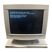
Do you have a question about the NEC MultiSync 3V JC-1535VMA/B/R and is the answer not in the manual?
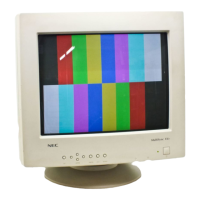
Identifies the specific NEC MultiSync monitor models covered by this manual.
Details the monitor's screen specifications, signal compatibility, and resolution.
Specifies power consumption, current rating, and environmental operating conditions.
Provides physical dimensions, weight, and cabinet details of the monitor.
Describes the monitor's control buttons and input signal connectors.
Details the pin assignments for various monitor and graphics board connectors.
Illustrates timing diagrams for separate and composite sync signals.
Presents timing data charts for different video signal inputs.
Explains the components and meaning of the monitor's serial number.
Details the function of each control used for monitor adjustments.
Steps for removing the tilt/swivel base and cabinet back.
Instructions for accessing and removing internal Printed Wiring Boards (PWBs).
Diagram showing the location of various PWBs within the monitor.
Diagrams and lists for connectors and test points on the Main PWB.
Diagrams and lists for connectors and test points on the I/F PWB.
Diagrams and lists for connectors and test points on the CRT PWB.
Lists compatible signals and required equipment for adjustments.
Details signal inputs and wiring for specific adapters like MAC II.
Specifies pin configurations for VGA and MAC II input connectors.
Describes the setup and connection for using the adjustment jig.
Comprehensive list of all adjustable parameters for the monitor.
Specifies the starting positions for various controls before adjustments.
Step-by-step guide for horizontal adjustments like hold and size.
Steps for adjusting vertical hold, linearity, and image position.
Procedures for adjusting pincushion, trapezoid, and focus.
Detailed steps for performing CRT purity and convergence adjustments.
Diagnostic steps for when the monitor displays no image.
Diagnosing problems related to high voltage and other power supply voltages.
Steps for identifying issues within the vertical deflection circuitry.
Diagnosing problems with the low B+ chopper and heater supply circuits.
Steps for diagnosing horizontal oscillator and synchronization problems.
Diagnosing various distortion problems including trapezoid and parallelogram.
Identifying failures related to user-adjustable controls like brightness and contrast.
Diagnosing blanking circuit failures and poor focus conditions.
Steps for diagnosing poor linearity and DC control circuit failures.
Checking IC supply voltages and diagnosing IPM (Intelligent Power Management) failures.
Diagnosing issues identified by the monitor's self-test function.
Description of the functional circuits on the I/F PWB.
Description of the functional circuits on the CRT PWB.
Description of the rectifying, smoothing, and auxiliary power supply circuits.
Description of oscillating, control, and protection circuits on the Main PWB.
Description of horizontal drive, B+ chopper, and related circuits.
Description of circuits for horizontal size, vertical, and pincushion controls.
Lists component differences between various monitor models.
Lists common replacement parts including ICs, transistors, and diodes.
Lists replacement resistors and capacitors with their specifications.
Lists replacement relays, switches, coils, filters, and appearance parts.
Diagram showing component placement on the Main PWB's solder side.
Diagrams showing component placement on the I/F and CRT PWBs' solder sides.
Diagrams showing component placement on control PWBs' solder sides.
Detailed circuit diagrams for the Main PWB.
Detailed circuit diagrams for the CRT PWB.
Detailed circuit diagrams for the Interface (I/F) PWB.
