Purity Adjustment
(1)
(2)
(3)
(4)
Be sure that the display is not being exposed to any external magnetic fields.
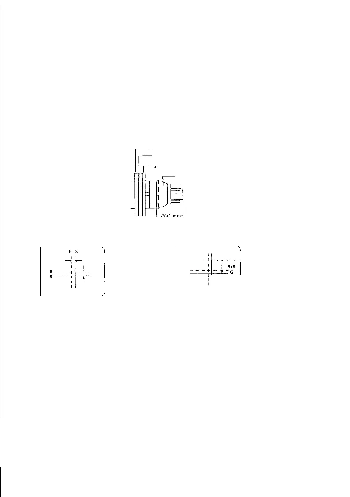
Ensure that the spacing between the Purity Convergence Magnet (PCM) assembly and the CRT stem is 29
mm±1
mm. (See diagrams below)
Produce a complete, red pattern on the screen. Adjust the purity magnet rings on the PCM assembly to obtain a
complete field of the color red. This is done by moving the two tabs in such a manner that they advance in an
opposite direction but at the same time to obtain the same angle between the two tabs, which should be
approximately
180°.
Check the complete blue and complete green patterns to observe their respective color purity. Make minor
adjustments if needed.
Ir
Purity
Magnets
4-pole
magnets
(Red
to
Blue
Convergence)
I-’
6 pole magnets
(Green
IO Magenta Convergence)
Purity,
Convergence Magnet Assembly (PCM)
7
Picture
Tube
-x
1
Perform
the
adjustment
by opening
the
angle
between
the
tabs.
;__-+i_-
1
;
I
Perform
the
adjustment
by synchronous
rotation of the two
tabs.
/
B/RG
\
Perform
the
adjustment by synchronous
rotation
of
the
IWO tabs.
1
Perform
the adjustmenl
by opening
the
angle
between
the
tabs
Red to Blue Convergence
:Green
to Magenta Convergence
(Magenta)
(White)
Convergence Adjustment
(1)
(2)
(3)
(4)
(5)
(6)
(7)
Produce a magenta crosshatch on the screen.
Adjust the focus for the best overall focus on the screen.
Also adjust the brightness to the desired condition.
Vertical red and blue lines are converged by varying the angle between the two tabs of the 4-pole magnets on
the PCM assembly. (See diagrams above)
Horizontal red and blue lines are converged by varying the two tabs together, keeping the angle between them
constant.
Produce a white
crosshatch
pattern on the screen.
Vertical green and magenta lines are converged by varying the angle between the two tabs of the 6-pole
magnets.
Horizontal green and magenta lines are converged by varying the two tabs together, keeping the angle
between them constant.
27