1-4. Low voltage chopper regulator circuit
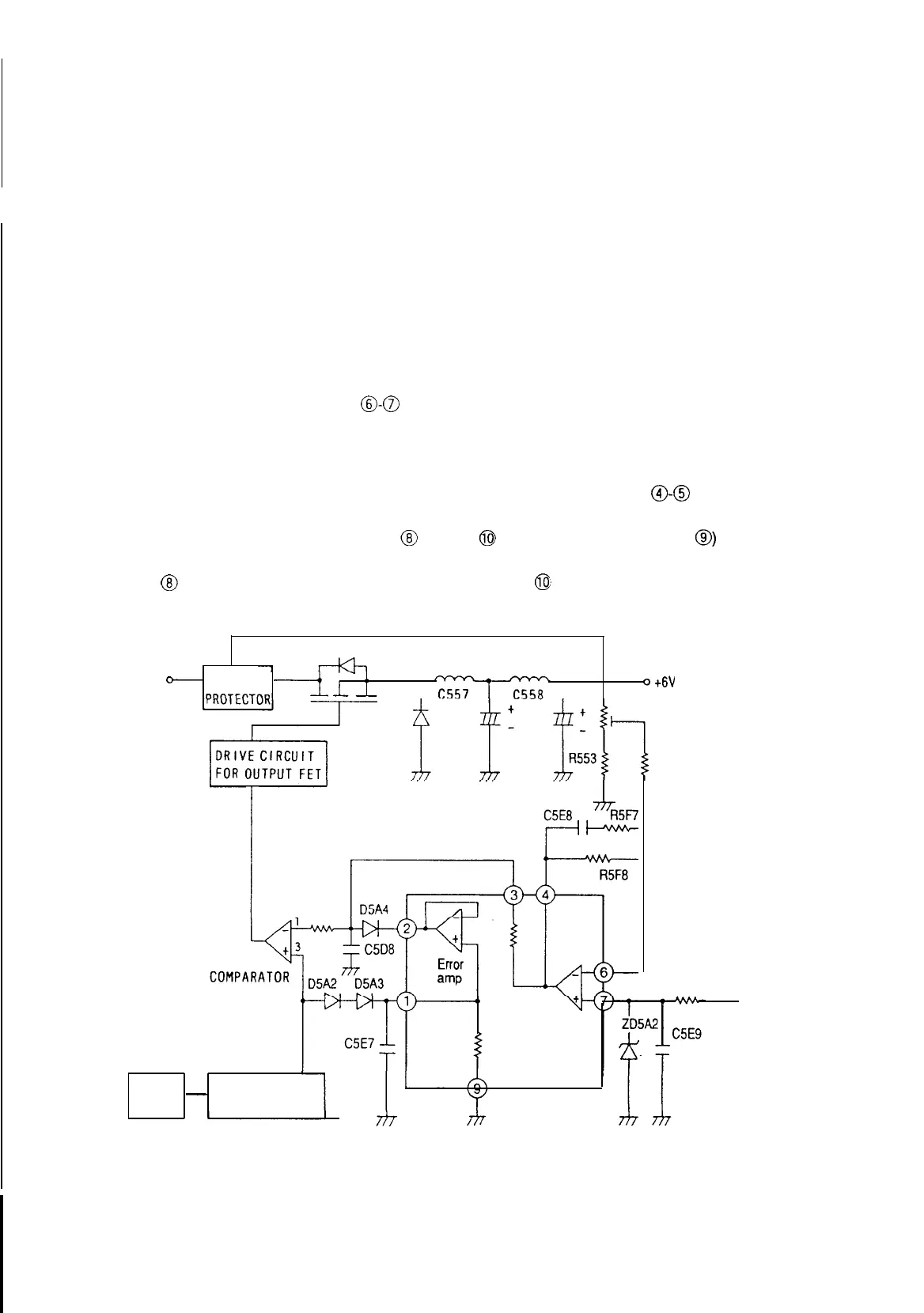
The low voltage chopper regulator circuit id PWM controlled and synchronized with the H deflection DC/DC
converter output of the DC/DC converter.
The pulse duty is determined by comparing the saw tooth waveform and the feedback voltage through error amp of
IC5A4
with a comparator of
IC5A3.
This feedback circuit is automatically controlled and generates constant and
stable output voltage.
If the H OSC operation stops, the output voltage will become low. The output voltage of 6V line is limited by low
+B
protector.
This circuit generates 6V power supply from the pulse of
T551’s
primary winding and
5V
power supply from the 6V
power supply by using 3 terminal regulator of lC864. By using the pulse induced in the secondary windings,
12V,
-
1 OV, -5V and horizontal raster centering power supply can be obtained.
As for
12V
power supply, it is obtained as below.
After adding the pulse induced between pin
B-0
of T551 and the generated +
6V,
it is rectified by D553 and
C561.
Then the rectified voltage of
13V
or a little more voltage is obtained.
12V
power supply is obtained from this voltage
by using
12V
4 terminal regulator of lC552.
As for -lOV power supply, it is obtained by rectifying the voltage induced between pin
a-0
of
T551
by D552 and
C559. As for -5V power supply, it is obtained by using zener diode and as for horizontal raster centering power
supply, it is obtained by rectifying the voltage of pin
@ and pin
@I
with their middle point (pin
@)
connected to the
+B
voltage of horizontal deflection.
The voltage of pin
@ is rectified by Q513 and C517. The voltage of pin
@
is rectified by D512 and C516.
Q552
T551
L551
+24V
-
Low
+B
ot6V
0551
1
IC5A3.
R5G7
VR551
+6V ADJ
R5F9
R5GO
SAW TOOTH
1C5A5
H OSC
-
GENERATOR
+24v
(Fig 1-4-1) BLOCK-DIAGRAM of the Low Voltage Chopper Regulator
47