Instructions
for Installer,
Maintenance Engineer
and final User
SINFONIA
Rev. 00
H4345 - 00 02/2013 Page 22 of 41
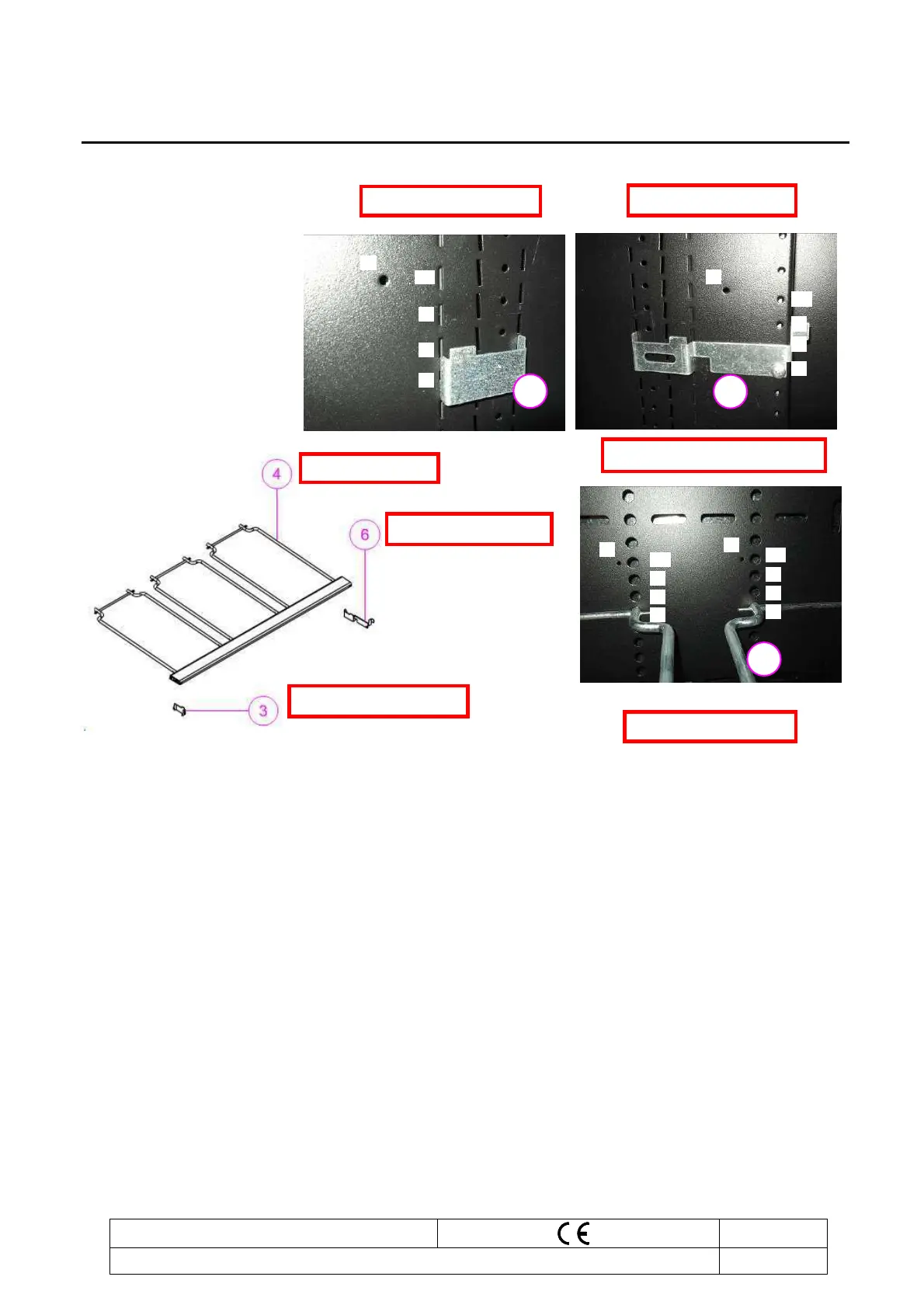
Shelf 1 is fixed. Counting starts from bottom with hole no. 1.
Ever
y 10th position is indicated by a reference Hole (indicated with “R” in the photo).
The shelf assy must be inserted into the same hole position as the shelf supports (See
example: Second shelf, position 7).
Position of shelf assy. in cabinet back panel: Hole no. 7.
Position of front shelf supports RH and LH: Hole no. 7.
Back panel internal Cabinet
6
4
3



 To Next Page