8Section 3: Installation Details
Section 3: Installation Details
3.1 Gas Requirements
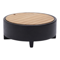
The fire table should be placed on a flat and level surface. It will arrive with the burner and burner plate set
inside the unit. Burner hardware has been installed at the factory but will need to be checked for proper
tightness after transportation. Refer to the corresponding section below for setup on your unit. All units
must have clearance to combustible surface of 4ft on sides & 6ft from the top. Refer to the section below
for the gas type you purchased.
3.1.1 Natural Gas
Gas Pressure: 7 inches water column Gas Input Flow: 65,000 BTU/HR
Prior to installation, a gas professional will need to run a gas line underground below the foundation where
your fire feature will reside. In order to do this, your gas professional will first need to determine the best
pipe size based on fuel input requirements (BTU’s/HR), gas pressure and distance from gas pressure
regulator to fire feature. Once you have created a trench underground for your pipe, the stubbed-out end
should be fitted with a 1/2" NPT ball valve shutoff (rated for gas usage) and a flare fitting sized for the
same size gas hose that is attached to the key valve and burner. Connect your flex hose to the stubbed-out
gas pipe then connect the other end to the key valve in your fire feature. The arrow on the key valve should
be pointing the direction of the gas flow (towards the burner plate on your fire feature). Tighten all fittings
with a wrench, do not hand tighten! Test the gas lines for leaks and loss of pressure over a 24-hour period.
When you are finished testing and have found no leaks, cover the pipes, level the ground and finish setting
the foundation. Once everything is tightly sealed and connected, gently place your burner plate back down
into your fire feature; your fire table is now ready to be positioned in its final location.
Note: Check with your gas supplier to verify gas flows and pressures available at the location of your
installation. In many cases utility companies will install larger meters at no charge to accommodate
larger flows.
3.1.2 Liquid Propane
Gas Pressure: 11 inches water column Gas Input Flow: 65,000 BTU/HR
Make sure the foundation is flat and level prior to placement. Units using liquid propane will come with a
burner, orifice, flex hose and regulator that will attach to the propane tank. This gas hose will need to go
from the tank to the burner. The hose should connect from the key valve within the unit, through a vent
underneath and to the propane tank. Make sure all fittings are tightened properly with a wrench, do not
hand tighten! An additional flex hose will be attached to the other end of the key valve to the flare fitting
at the bottom of the burner. The arrow on the key valve should be pointing the direction of the gas flow
(towards the burner plate on your fire feature).
Fire features do not include propane cylinder; you will need to provide one. The liquid propane supply
cylinder must be constructed and marked in accordance with the specifications for propane gas cylinders
as required by the U.S. Department of Transportation (DOT).