Section 4: Troubleshooting
4- 3
Table 4-1: Troubleshooting Guide (Continued)
Symptom Probable Cause Corrective Action
The unit does not
turn on when the
On/Off key is
pressed.
(continued)
The sensor is
defective.
Replace the sensor.
The front panel
keypad is defective.
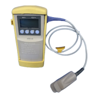
Open the NPB-40, disconnect
the case top from J3 on the CPU
PCB and connect an ohmmeter
between the flex circuit
conductor for J3, pin 5 and the
conductor for J3, pin 3. Observe
a short when the On/Off key is
pressed and an open when not
pressed. If incorrect, replace
case top. If all keys function
correctly, replace CPU PCB.
Caution: Unlock J3 before
attempting to remove flex
circuit conductor.
Flex circuit between
front panel and CPU
PCB is disconnected.
Inspect the flex circuit between
the front panel and the CPU
PCB and reconnect if loose.
A CPU PCB
component has
failed.
Inspect the CPU PCB
components and circuit board
for cracking, burning, or
damage, and replace the CPU
PCB if any are found. If any
failed components are observed,
replace CPU PCB.
Replace the CPU PCB with a
known good PCB.
One or more keys
on the front panel
keypad does not
work.
The front panel
keypad is defective.
Open the NPB-40, disconnect
the case top from J3 on the CPU
PCB and connect an ohmmeter
lead to the flex circuit conductor
for J3, pin 3. Refer to the front
panel schematic diagram and
individually connect the other
ohmmeter lead to each
conductor for the other keys.
Observe a short when the key is
pressed and an open when not
pressed. If incorrect, replace
case top. If correct, replace the
CPU PCB.
Caution: Unlock J3 before
attempting to remove flex
circuit conductor.
Flex circuit between
front panel and CPU
PCB is disconnected.
Inspect the flex circuit between
the front panel and the CPU
PCB and reconnect if loose.
(Continued on next
page)
A CPU PCB
component has
failed.
Inspect the CPU PCB
components and circuit board
for cracking, burning, or damage
and replace the CPU PCB if any
are found.