Technical Supplement
S-13
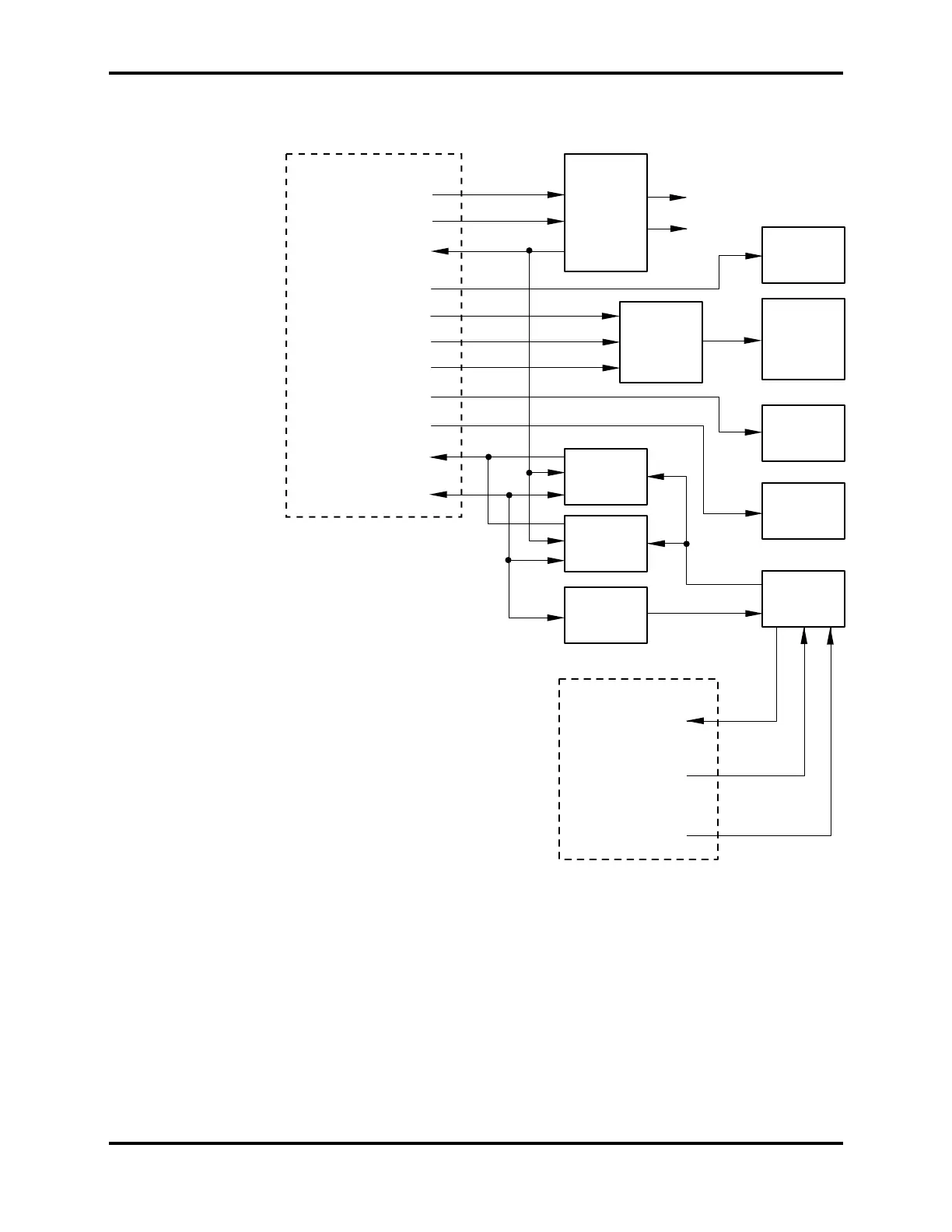
The relationship between these subsections is shown in the LCD PCB block
diagram, Figure S3-3.
LCD
driver
LCD
Beeper
Printer
IR LED
LCD
backlight
Power
conditioning
To/from patient sensor
Red
channel
IR
channel
LED
drive
Raw +10 Vdc
Raw -5 Vdc
V ref
+10Vdc
-5 Vdc
LCD data
LCD enable
Sensor
D-connector
Printer
LED signal
Beeper drive
LCD light enable
Analog sensor
signal
control signals
Analog circuit
To/from CPU PCB
LED drive
RSENS
Photodiode
LCD clock
Figure S3-3: LCD PCB Block Diagram
S3.3.1 Sensor Output/LED Control
The SpO2 analog circuitry provides control of the red and IR LEDs such that
the received signals are within the dynamic range of the input amplifier.
Because excessive current to the LEDs will induce changes in their spectral
output, it is sometimes necessary to increase the received signal channel
gain. To that point, the CPU controls both the current to the LEDs and the
amplification in the signal channel.