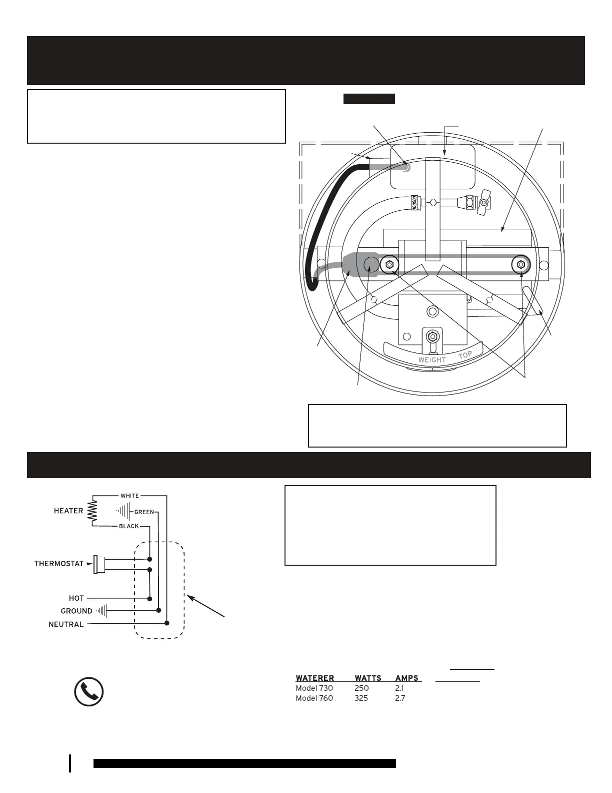
HEATER & THERMOSTAT INSTALLATION DIAGRAMS
STRAIN RELIEF CONNECTOR
ELECTRICAL
JUNCTION BOX
WATER
SPOUT
TUBE
HEATING
ELEMENT
(BELOW
CROSS BEAM)
HOLE IN
CROSS BEAM
HEAT SHEILD
CERAMIC
INSULATORS
THERMOSTAT
ELECTRICAL JUNCTION BOX COVER:
• Replace old cover with new cover provided with heaters & thermostats.
THERMOSTAT IS LOCATED IN ELECTRICAL JUNCTION BOX
AS INDICATED IN DIAGRAM.
STRAIN RELIEF CONNECTOR PREVENTS HEATER CORD FROM BEING
PULLED OUT OF JUNCTION BOX. SEE INSTRUCTIONS BELOW.
•Locate Connector on heater cord with large head of Connector on heating
element side. Allow enough cord on junction box side for wire
connections to be made inside junction box.
•Insert Connector and heater cord in junction box (as indicated in
diag
ram) using pliers and fingers until Connector snaps in place.
•Test by pulling on heater cord toward heating element. Connector and
heater cord should not pull out of junction box.
POWER SUPPLY MUST PROVIDE:
•A HOT wire which is connected to remaining BLACK wire of thermostat.
•A NEUTRAL wire which is connected to WHITE wire of heater.
•A GROUND wire which mu
st be connected to the ground screw in the
handy box. This will ground both the waterer and the heating element.
INTENDED USE:
• Thermostat Part 758 is designed for both Models 730 & 760.
• Heater Parts 755C & 755HA are designed for Model 730 Waterers only.
• Heater Parts 785C & 785HA are designed for Model 760 Waterers only.
• Heater’s Parts 755C & 785C come with Heating Element, Heat Shield,
Ceramic Insulators, Strain
Relief Connector and Cover for Junction Box.
• Do not use for any other application.
WAR NING! ELECTRICAL INSTALLATION
& MAINTENANCE
HEATER #
755
785
A LICENSED ELECTRICIAN WILL DETERMINE:
A) Type and size of service wire, B) grounding procedure,
and C) proper fusing of heater.
GROUND WIRE:
The heating element is grounded to the
waterer by a green ground screw at the factory. The ground wire
from the power service should be secured to the waterer with
the second green ground screw provided in the handy box. When
using wire-nuts, follow instruction on wire-nut box. Tape wire
nuts to wire to prevent loosening.
FUSING:
Waterers must be individually fused. Do not over fuse.
Consult a licensed electrician. Heating rating @ 120 volts AC.
DEDICATED CIRCUITS
– Waterers must be on dedicated
circuits. TURN POWER OFF after the Winter heating season when
heaters are no longer needed (temperatures are consistently
above freezing) or when performing maintenance on waterers.
Use a licensed electrician to install and maintain the
Waterer, so you can be assured that you have complied
with all national and local electrical codes and that you
have not created a risk of electrocution or fire. Improper
installation or maintenance may result in serious injury or
death for personnel or animals or damage to structures.
Heater & Thermostat Wiring Diagram
WARNING! TURN OFF ELECTRICITY WHEN SERVICING WATERER
Always turn off power to waterers whenusing a tool to service or
maintain waterer to eliminate risk of electrocution. Waterers should be on
dedicated circuits.
WARNING! USE CARE NOT to spill water on heating element. Water on
heating element reduces heater life and may lead to freeze-up. Keep area
below drinking bowl as dry and clean as possible.
TOP VIEW: COVER & BOWL REMOVED
ELECTRICAL
JUNCTION BOX
QUESTIONS?
Phone: 888-844-6606
Monday-Friday 7:30-5:00 CST
10
 Loading...