INSTALLATION INSTRUCTIONS
Power
supply cables
and cords used ioT connections
are to be a minimum oi ordlnary duly or
greater
duly. Live sLrpply
wires should be attached together
adiacent to the terminal block. Low
voltage outpul cables
irom the contro ler should be enclosed in conduit
affixed to contro ler with a
suitable adapter. Wiih lront
panel
open to
provide
access to the iniernal
transiormer bring 120V
(230/24A
Iot 8574, a576, 8578,
8582) wires up ihrough 1/2 conduit
into the left hole in the bottom
of the case.
(For
iield connecuon,
AC wires must have an insulation rated at
75'
C
minimum-)
Conduit shou d be secured to the case
(iolow
local
codes).
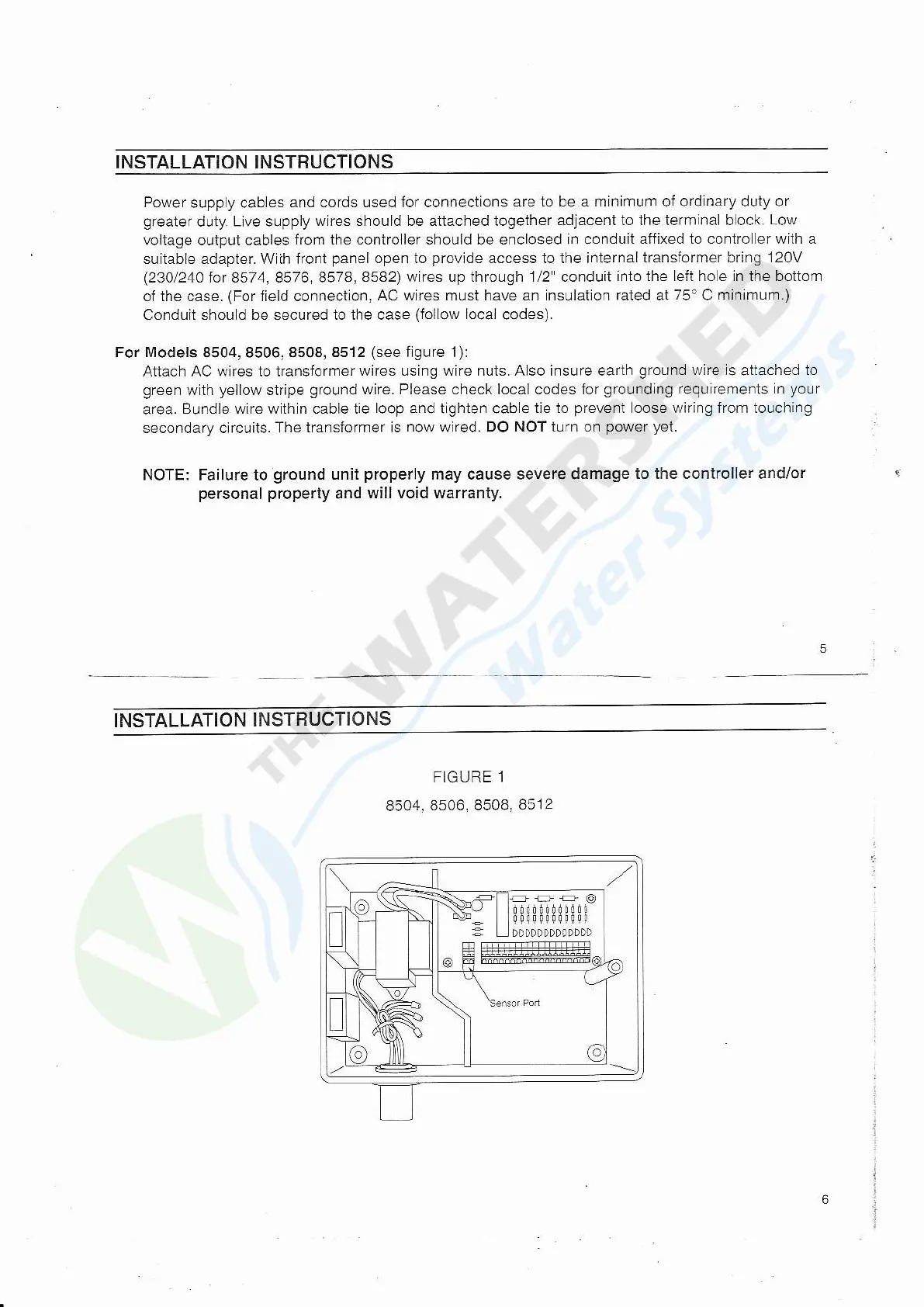
For Models
8504,8506,8508,8512
(see
figure 1):
Atiach AC wites to ttansiormer
wires using wire nuls. Aso insuTe earth
ground
wire rs
attached
to
green
wlth
yeilow
slripe
ground
wire. Please check local codes for
groLrndlng
reqLl remenls n
your
area.
B!ndle wire wthln cable tie
loop and
t
ghlen
cab
e tie to
prevent
oose wiring from louching
secondary clrcuits.
The transforrner is
now
wired.
DO NOT i!rn on
power yet.
NOTE: Failure to
ground
unit
properly
may cause severe damage
to the controller and/or
personal property
and
will void warranty.
INSTALLATION
INSTRUCTIONS
FIGURE 1
8504,8s06,
8508,8512