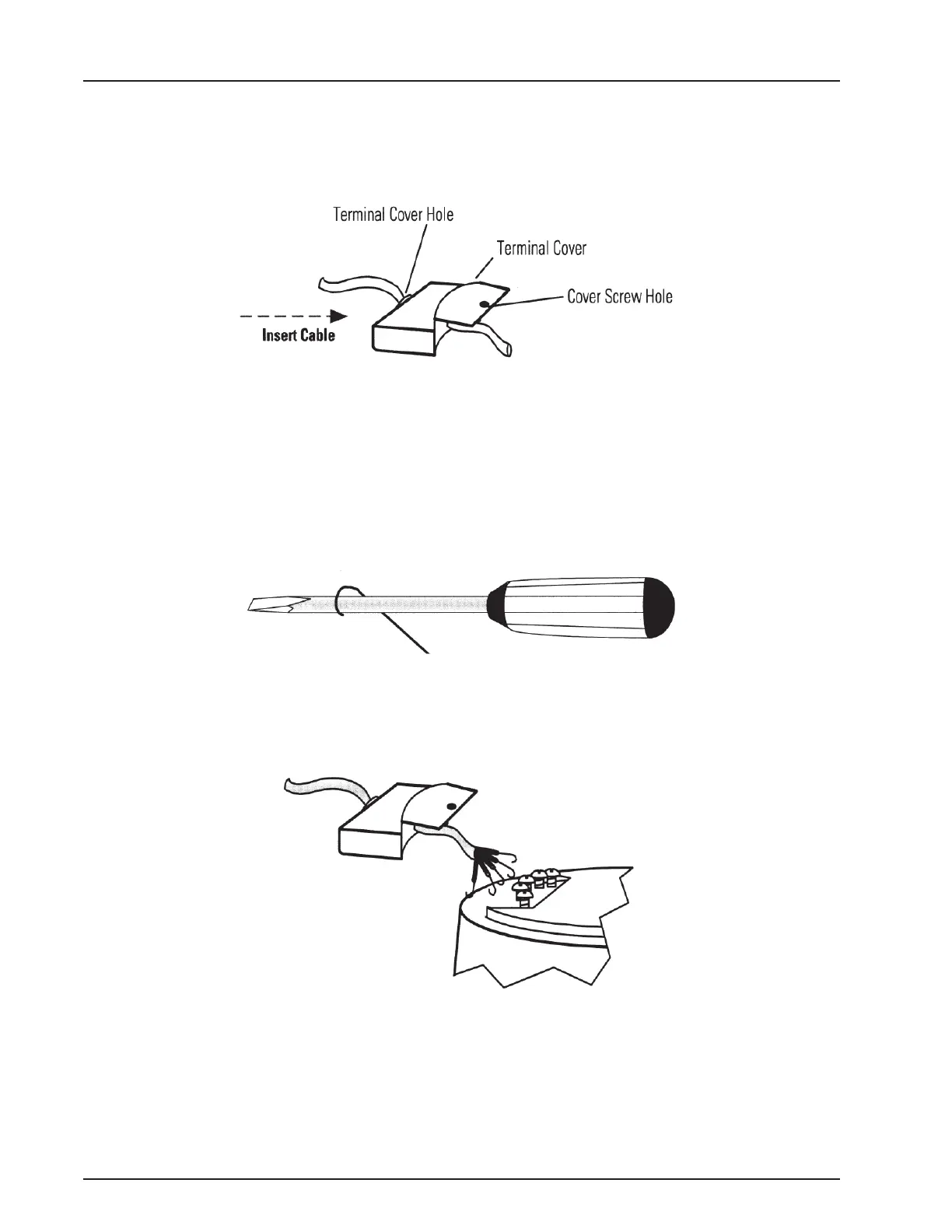
3. Insert the end of the multi-conductor cable through the hole in the terminal cover as
shown in the previous figure. Move the cover far enough down the cable to allow you to
work with the end that you just inserted.
Figure 2 – Elements of the Transmitter
4. Strip the outer covering of the cable back approximately 1½” from the inserted end.
5. Separate the individual conductors and strip the insulation back approximately ½” from
the end of each conductor.
6. Using the rounded shaft of the screwdriver, form a hook in the end of each bare copper
wire.
Figure 3 – Creating a Hook in the Wire
7. Loosen the terminal screws.
Figure 4 – Connecting the Conductors
8. Position the wire hook of each conductor under the proper terminal screw according to
the wiring diagram.
TRICON
®
E/E2/E3 Installation and Maintenance Guide 11
Chapter 3: Installing the Transmitter