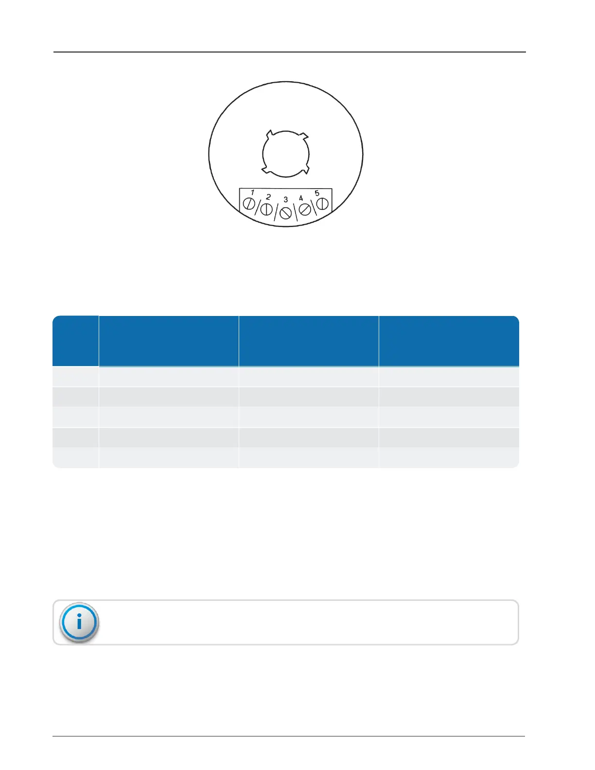
Figure 5 – TRICON
®
/E/E2/E3 Wiring
PIN #
TRICON
®
/E Digital Pulse (Prior
to 1/96)
TRICON
®
/E2 and E3 Model
Digital Pulse Model
(after 1/96)
TRICON
®
/E, E2 and
TRICON
®
/E3
4-20MA Models
1 No Connection High Resolution Output 4-20mA Source (+)*
2 No Connection Count Direction
1
4-20mA Return (–)
3 12-24VDC Power In (+) 12-24VDC Power In 24VDC Power In (+)
4 Common Ground (– side) Common Ground (– side) Common Ground (– side)
5 Pulse Output Pulse Output Pulse Output
Table 11 – TRICON
®
E/E2/E3 Wiring Codes
*The (+) indicates conventional current exiting the TRICON.
1
This connection is a contact closure to ground and requires DC power supplied through a pull-up resistor.
Typical pull-up resistor values are 2K per 5 volts of the DC voltage.
9. Place each wire hook so that it runs in a clockwise direction around the screw terminal,
with no insulation under the screw head.
10. Use the tip of the screwdriver to close the hooks around the terminal screws and tighten
the screws until snug.
Take care not to overtighten the terminal screws when completing the wiring.
12 TRICON
®
E/E2/E3 Installation and Maintenance Guide
Chapter 3: Installing the Transmitter