NGP\00329 Rev. C 23-06-2006 Evolution Series - XPAND 13
2. SYSTEM DESCRIPTION
The Evolution Series microwave radio system comprises an indoor part (IFU), and an outdoor part
(ODU) and an antenna. The IFU and ODU is interconnected with coaxial cable which carries transmit and
receive user traffic, management communication between the IFU and ODU, and the power supply to the
ODU.
2.1. IFU with PDH X-Connect
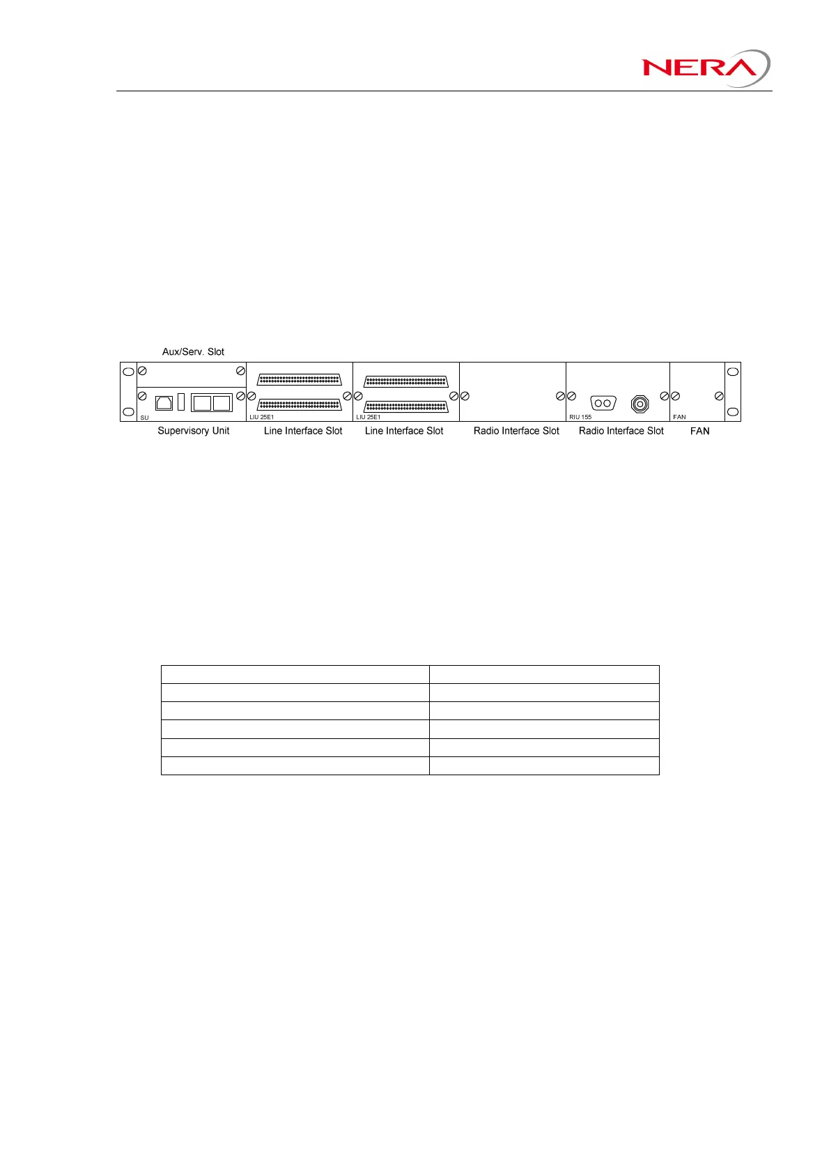
The Evolution Series IFU is a 1RU basic frame, containing 9 plug-in slots for various modules. The
modular architecture with plug-in slots enables a high degree of flexibility, ease of upgrading/changing
configurations and easy maintenance.
Figure 2-1 IFU, 1+0 system
The basic IFU frame is common in all configurations and up to four basic IFU basic frames can be
stacked together through a rear connection. Cages with connection panel housing 2 or 4 IFUs are
available.
Embedded 4-port X-connect for routing of E1/T1 and Ethernet traffic:
The basic IFU frame contains an embedded 4-port PDH X-Connect (PXC). Each of these 4 ports (0, 1, 2
and 3) can be assigned to the Ethernet Interface (on Supervisory Unit), E1/T1-Line Interface Unit, Radio
Interface Unit, or IFU-rear-interface (IFU expansion). Ethernet traffic is carried as E1/T1-frames through
the X-connect. The capacity through the 4 PXC-ports is limited by the unit each port is connected to as
shown in the table below:
PXC connected to: Maximum Capacity:
Ethernet port (on SU Unit) 50E1 or 64T1 (100Mb/s)
E1 Line Interface 25E1
T1 Line Interface 16T1
Radio Interface 75E1 or 96T1
IFU rear Interface (IFU expansion) 63E1 or 84T1
Each of the E1/T1 carried through the 4 PXC-ports can be X-connected (any to any, non-blocking). Each
E1/T1-output from the PXC can be configured to be sourced from any E1/T1-input. All E1/T1-outputs
may have the same source (one-to-many principle). Two of the PXC-ports (port 2 and 3) can be
configured to go to Radio Interfaces. SNCP is available for each E1/T1. When configuring the PXC,
each individual E1/T1 may be set up with SNCP activated or not activated.