- 18 -
9-Pin Accessory
Connector
RS232 Pin Connections
Pin # Function
1 No connection.
2 TX = Transmitted data
3 RX = Received data
4 No connection
5 GND = Signal ground
6 No connection.
7 CTS = Clear to send
8 RTS = Request to send
9 No connection
Hardware Internal Connector Mating Connector
AMP Part# 745491-2 AMP Part# 745492-2
Remote Sensor Connections
Pin # Function
1 3-wire RTD connection A
2 No connection
3 No connection
4 3-wire RTD connection B
5 No connection
6 No connection.
7 No connection
8 No connection
9 3-wire RTD connection C
Hardware Internal Connector Mating Connector
AMP Part# 745491-2 AMP Part# 745492-2
5 4 3 2 1
9 8 7 6
RS-232
5 4 3 2 1
9 8 7 6
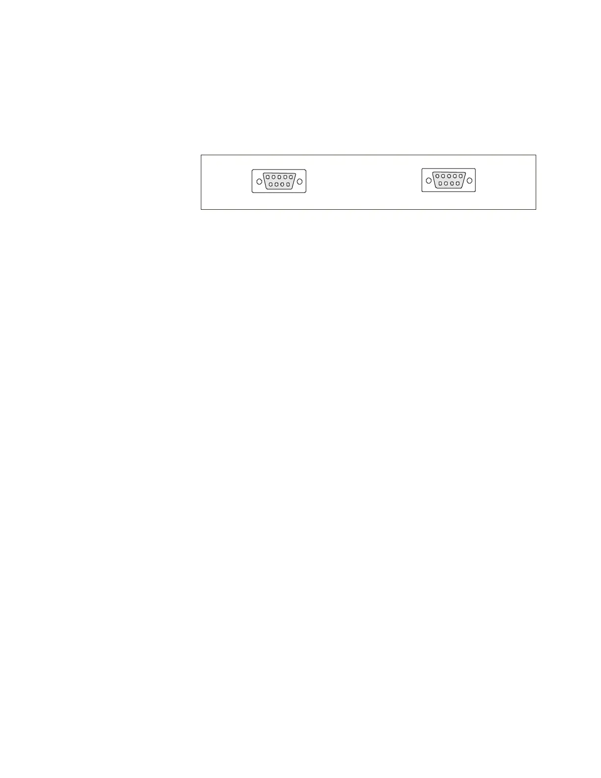
The unit is equipped with two female 9-pin D-connectors located on the rear of
the control box. One is used for RS232 communication, the other is used with
an optional remote sensor.
REMOTE
SENSOR