vi
Table of Figures
Figure 1: L300 System Components ................................................................. 7
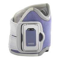
Figure 2: The Orthosis ........................................................................................ 8
Figure 3: Foot Sensor ....................................................................................... 10
Figure 4: Control Unit........................................................................................ 12
Figure 5: Positioning the Leg ............................................................................ 20
Figure 6: Placing the Orthosis on the Leg ........................................................ 21
Figure 7: Fastening the Strap ........................................................................... 22
Figure 8: Orthosis Fastened in Place ............................................................... 23
Figure 9: Control Unit Charger Socket.............................................................. 28
Figure 10: Charging the Batteries..................................................................... 28
Figure 11: Charging Indicators ......................................................................... 28
Figure 12:Foot Sensor and Battery................................................................... 30
Figure 13: Control Unit and Battery .................................................................. 30
Figure 14: Digital Display while Registering ..................................................... 34
Figure 15: Removing the electronic module from the orthosis......................... 35
Figure 16: Foot Sensor in Place (Left Shoe Shown)........................................ 36
Figure 17: Transmitter in Place on a Right Shoe.............................................. 37