As you insert the connector, you should feel it click into place; if you do not feel it click, remove
it, turn it around and try again.
Step Perform on each controller module
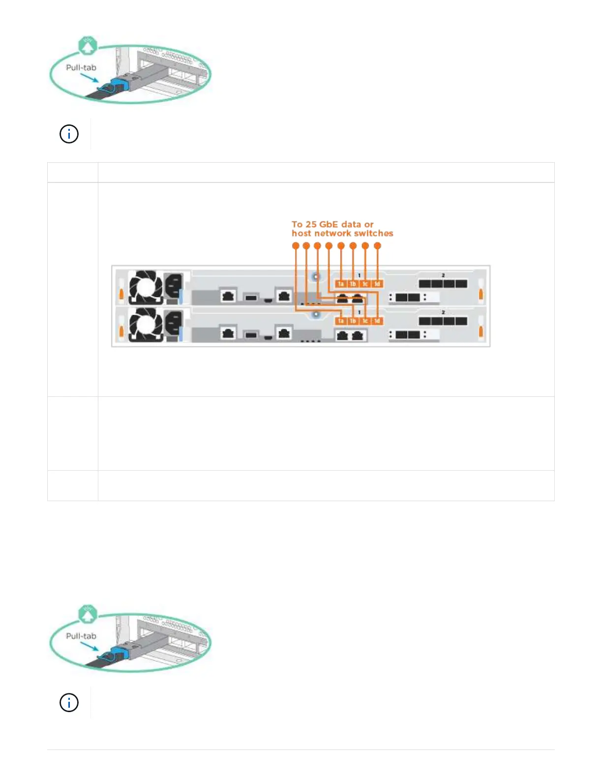
1 Cable ports e4a through e4d to the 10GbE host network
switches.
2 To perform other optional cabling, choose from:
•
Option 1: Cable to a Fibre Channel host network
• Option 3: Cable the controllers to a single drive shelf
3 To complete setting up your system, see Step 4: Complete system setup and configuration.
Option 3: Cable the controllers to a single drive shelf
Cable each controller to the NSM modules on the NS224 drive shelf.
Before you begin
Be sure to check the illustration arrow for the proper cable connector pull-tab orientation.
As you insert the connector, you should feel it click into place; if you do not feel it click, remove
it, turn it around and try again.
286