into the slots on the battery pack, and the battery pack latch engages and locks into place.
b. Press firmly down on the battery pack to make sure that it is locked into place.
c. Plug the battery plug into the riser socket and make sure that the plug locks into place.
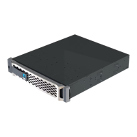
Step 9: Install a PCIe riser
To install a PCIe riser, you must follow a specific sequence of steps.
1. If you are not already grounded, properly ground yourself.
2. Install the riser into the controller module:
a. Align the lip of the riser with the underside of the controller module sheet metal.
b. Guide the riser along the pins in the controller module, and then lower the riser into the controller
module.
c. Swing the locking latch down and click it into the locked position.
When locked, the locking latch is flush with the top of the riser and the riser sits squarely in the
controller module.
d. Reinsert any SFP modules that were removed from the PCIe cards.
3. Repeat the preceding steps for Riser 3 and PCIe cards in slots 4 and 5 in the impaired controller module.
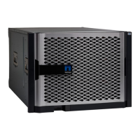
Step 10: Move the power supply
You must move the power supply and power supply blank from the impaired controller module to the
replacement controller module when you replace a controller module.
1. If you are not already grounded, properly ground yourself.
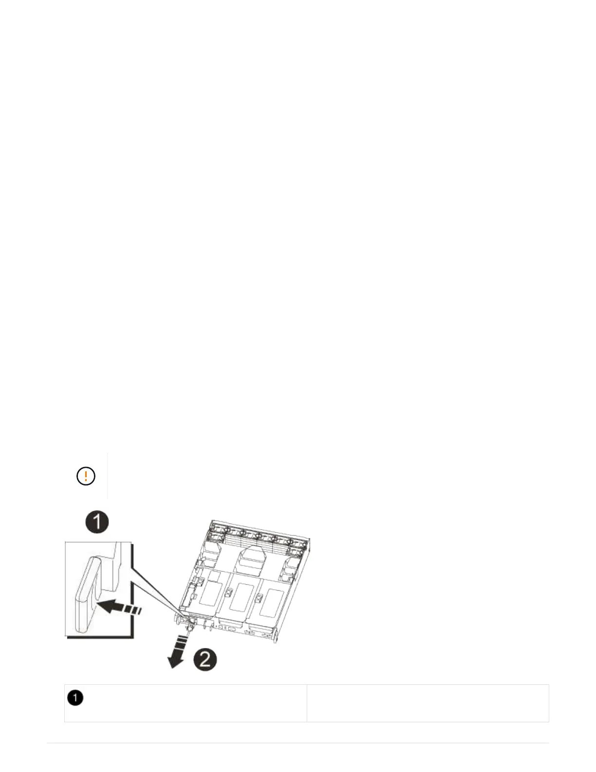
2. Rotate the cam handle such that it can be used to pull power supply out of the controller module while
pressing the locking tab.
The power supply is short. Always use two hands to support it when removing it from the
controller module so that it does not suddenly swing free from the controller module and
injure you.
Blue power supply locking tab
879