Security Gateway Manual SG-3100
Switched Ethernet
Interface Name Port Name Port Type
LAN1 mvneta1 RJ-45
LAN2 mvneta1 RJ-45
LAN3 mvneta1 RJ-45
LAN4 mvneta1 RJ-45
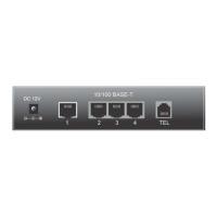
The four LAN Ethernet ports are switched ports. By default all of these ports as a single switch uplinked to the LAN
interface on the firewall.
Note: For more details on how the switch operates, see Switch Overview.
For instructions on how to configure the switch see Configuring the Switch Ports.
Table 2: RJ-45 LEDs Configuration
LED Pattern Description
Both LEDs green Left Flashes with 1 Gb traffic, solid with link.
Left LED only green Left flashes with 100 Mb traffic, solid with link.
Right LED only green Left Flashes with 10 Mb traffic, solid with link.
Note: Prior to pfSense® software version 2.4.3, the switched Ethernet ports on the SG-3100 did not support auto
MDI-X and required crossover cable unless the client-side connection supported auto MDI-X. This was resolved with
2.4.3 and later versions and a crossover cable is no longer required.
Warning: The LAN ports do not support the Spanning Tree Protocol (STP). Two or more ports connected to
another Layer 2 switch, or connected to 2 or more different interconnected switches, could create a flooding loop
between the switches. This can cause the router to stop functioning until the loop is resolved.
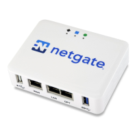
Other Ports
1. Power
• 12VDC 3.33A with threaded locking connector
• Power Consumption 5W (idle)
2. Recessed Reset Button (performs a hard reset, immediately turning the system off)
3. USB 3.0 Port
4. Micro SIM
5. Mini-USB Serial Console
Warning: A hard reset of the system could cause data corruption and should be avoided. Halt or reboot the
system through the console menu or the GUI to avoid data corruption.
© Copyright 2022 Rubicon Communications LLC 13
 Loading...