Do you have a question about the NETGEAR GS208 and is the answer not in the manual?
Connect computers and servers to the switch for network access.
Connect optional router and modem for internet access.
Indicates the power status of the switch.
Shows Ethernet link and activity status for each port.
Details the RJ-45 connector types supported.
Specifies the required Ethernet cable category.
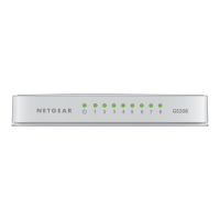
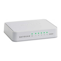
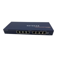
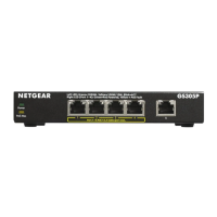
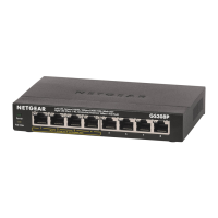
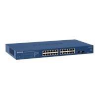
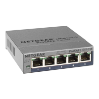
Lists the number of ports for GS205 and GS208 models.
Information on power input and consumed wattage.
Provides physical size and weight for both models.
Specifies temperature and humidity limits.
Instructions for registering the product for support.
Links for product updates and web support.
This document serves as an installation guide for the NETGEAR GS205 and GS208 Gigabit Switches, offering a straightforward approach to setting up and maintaining these networking devices. The guide outlines a four-step process, beginning with the physical placement of the switch, followed by equipment connection, power hookup, and finally, status verification. This structured approach ensures that users can quickly and efficiently integrate the switch into their existing network infrastructure.
The first step, "Position switch," emphasizes the importance of proper placement for optimal performance and longevity of the device. The guide illustrates two key considerations: ensuring adequate ventilation and avoiding obstructions. One image depicts a switch with radiating lines, symbolizing the need for clear airflow around the device to prevent overheating. This is crucial for maintaining stable operation and extending the lifespan of the switch. Conversely, another image shows a switch with a red "X" over stacked objects, indicating that the switch should not be placed in confined spaces or stacked with other equipment that could impede ventilation. Proper positioning not only helps dissipate heat but also ensures that the ports are easily accessible for cable management.
The second step, "Connect equipment," details how to integrate the switch into a network. This step is visually supported by a diagram showing a typical home or small office network setup. The GS208 switch is centrally located, connecting various devices such as a computer, a server, an optional modem, and an optional router. This setup highlights the switch's role as a central hub for wired connections, allowing multiple devices to share a single internet connection or communicate within a local network. The diagram uses green lines to represent Ethernet cables, illustrating the flow of data between the switch and the connected devices. This visual aid simplifies the connection process, making it easy for users to understand where each cable should go. The flexibility to connect to an optional modem and router underscores the switch's adaptability to different network configurations, whether it's expanding an existing network or building a new one from scratch.
The third step, "Connect power," is a critical but simple task. The guide provides a clear illustration of how to connect the power adapter to the switch and then to a power outlet. This step is essential for powering on the device and making it operational. The illustration shows the power adapter connected to the switch's power input, with the other end plugged into a standard wall socket. This straightforward connection ensures that the switch receives the necessary electrical supply to function correctly. Without proper power, the switch cannot perform its networking duties, making this step fundamental to the installation process.
The final step, "Check status," focuses on verifying that the switch is operating as expected through its LED indicators. The guide provides a detailed explanation of the Power LED and Port LEDs, which serve as visual cues for the device's operational status. The Power LED indicates whether the switch is on or off. A green light signifies that the switch is powered on and ready for use, while an unlit LED means it is off. The Port LEDs offer more granular information about individual Ethernet connections. Each port has its own LED, which can display three different states: an Ethernet link, activity (blinking), or no link (off). A solid green light on a Port LED indicates that an Ethernet link has been established with a connected device, meaning the physical connection is sound. A blinking green light signifies network activity, indicating that data is being transmitted or received through that specific port. If a Port LED is off, it means there is no active link detected, which could indicate a disconnected cable, a problem with the connected device, or an issue with the cable itself. Understanding these LED indicators is crucial for troubleshooting common network issues and ensuring that all connections are functioning correctly. This diagnostic feature allows users to quickly identify and address problems without needing specialized tools or software.
In summary, the NETGEAR GS205/GS208 Installation Guide provides a user-friendly and comprehensive approach to setting up these Gigabit switches. From strategic placement to verifying operational status through LED indicators, each step is designed to be intuitive and easy to follow. The emphasis on proper ventilation, clear connection diagrams, and detailed LED explanations ensures that users can confidently install and maintain their network switches, thereby enhancing their network's performance and reliability. The guide's clear instructions and visual aids make it an invaluable resource for both novice and experienced users looking to expand or optimize their wired network connections.
| Switch type | Unmanaged |
|---|---|
| Switch layer | - |
| Power connector | DC-in jack |
| Basic switching RJ-45 Ethernet ports type | Gigabit Ethernet (10/100/1000) |
| Basic switching RJ-45 Ethernet ports quantity | 8 |
| 10G support | No |
| Auto MDI/MDI-X | Yes |
| Networking standards | IEEE 802.3ab, IEEE 802.3az, IEEE 802.3i, IEEE 802.3u, IEEE 802.3x |
| Copper ethernet cabling technology | 1000BASE-T, 100BASE-TX, 10BASE-T |
| MAC address table | 4000 entries |
| Packet buffer memory | 1.5 MB |
| Certification | CE, CB, C-Tick |
| Product color | White |
| LED indicators | Activity, Link, Power |
| Housing material | Plastic |
| Input current | 1 A |
| Input voltage | 12 V |
| Power consumption (typical) | 3.64 W |
| Number of power supply units | 1 |
| Operating temperature (T-T) | 0 - 40 °C |
| Operating relative humidity (H-H) | 10 - 90 % |
| Package depth | 225 mm |
| Package width | 190 mm |
| Package height | 59 mm |
| Package weight | 470 g |
| Shipping (inner) case width | 486 mm |
| Shipping (inner) case height | 434 mm |
| Shipping (inner) case length | 329 mm |
| Shipping (inner) case net weight | 10560 g |
| Number of layers per pallet (air) | 3 pc(s) |
| Number of layers per pallet (sea) | 4 pc(s) |
| Number of cartons per pallet layer | 7 pc(s) |
| Quantity per shipping (inner) case | 20 pc(s) |
| Depth | 93 mm |
|---|---|
| Width | 152 mm |
| Height | 26 mm |
| Weight | 190 g |