Do you have a question about the NETGEAR WAX218 and is the answer not in the manual?
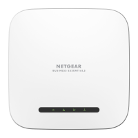
Details the access point model and included mounting bracket, screws, and anchors.
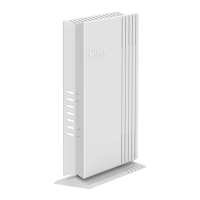
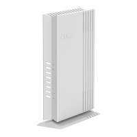
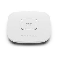
Details the WAX218 hardware, including LEDs, reset button, LAN/PoE+ port, and DC connector.
Instructions for powering up the WAX218 via a PoE+ switch and network connection.
Steps to connect a device to the WAX218's default WiFi network using the provided passphrase.
Guide to accessing and logging into the WAX218's local browser user interface.
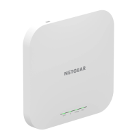
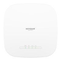
Explanation of LED colors and patterns for Power, LAN, 2.4 GHz WLAN, and 5 GHz WLAN.
Information on accessing user manuals for alternative configuration methods.
Links to NETGEAR support website and community forum for assistance and downloads.
Information on regulatory compliance, privacy policy, and terms and conditions.
Detailed steps for mounting the access point securely to a solid wall.
Instructions for attaching the access point to a standard 15/16 inch T-bar ceiling mount.
Steps for attaching the access point's mounting bracket to a solid ceiling surface.
| 2.4 GHz | Yes |
|---|---|
| Number of users | 256 user(s) |
| Networking standards | IEEE 802.11a, IEEE 802.11ac, IEEE 802.11ax, IEEE 802.11b, IEEE 802.11e, IEEE 802.11g, IEEE 802.11n |
| Ethernet LAN data rates | 1000, 2500 Mbit/s |
| Maximum data transfer rate | 3600 Mbit/s |
| Maximum data transfer rate (5 GHz) | 2400 Mbit/s |
| Maximum data transfer rate (2.4 GHz) | 1200 Mbit/s |
| Placement | Ceiling, Wall |
| Product color | White |
| Output voltage | 12 V |
| Power over Ethernet (PoE) | No |
| USB 2.0 ports quantity | 0 |
| Ethernet LAN (RJ-45) ports | 1 |
| Cables included | LAN (RJ-45) |
| Number of products included | 1 pc(s) |
| Storage temperature (T-T) | -40 - 75 °C |
| Operating temperature (T-T) | 0 - 40 °C |
| Operating relative humidity (H-H) | 5 - 95 % |
| Security algorithms | WPA, WPA2, WPA3 |
| Number of SSID supported | 4 |
| Antenna type | Internal |
| Antenna gain level (max) | 5 dBi |
| Width | 205.73 mm |
|---|---|
| Height | 34.75 mm |
| Weight | 788 g |