Page 2
NetworX NX Series Receiver Modules
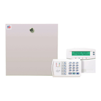
3) Install the module into the cabinet by turning the stand-
off sideways, then slide the module up onto the ground
plane screw posts (see Figure 3).
Figure 3. Installing the Module into the Cabinet
4) Turn the standoff so the slot is facing up, insert the
back corner of the module into the standoff slot, then
press up at the front of the standoff and tighten the
standoff screw.
5) Insert the antennas through the holes on top of the cab-
inet and into the module antenna sockets (see Figure
4).
Figure 4. Inserting the Antennas
Wiring, Module Number DIP Switch
Settings, and Power Up
The following steps describe wiring the module to the NX-
8, setting the module number DIP switches, and powering
up the NX-8.
1) Remove power (if applied) from the NX-8 control
panel.
CAUTION: To avoid possible equipment damage or per-
sonal injury, remove power from the NX-8
control panel before making any wiring con-
nections to the module.
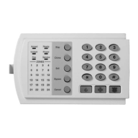
2) Connect the module power and data terminals to the
NX-8 power and data terminals using 22-gauge or
larger, stranded wire (see Figure 5).
Figure 5. Wiring the Module Power and Data Terminals
to the NX-8 Power and Data Terminals
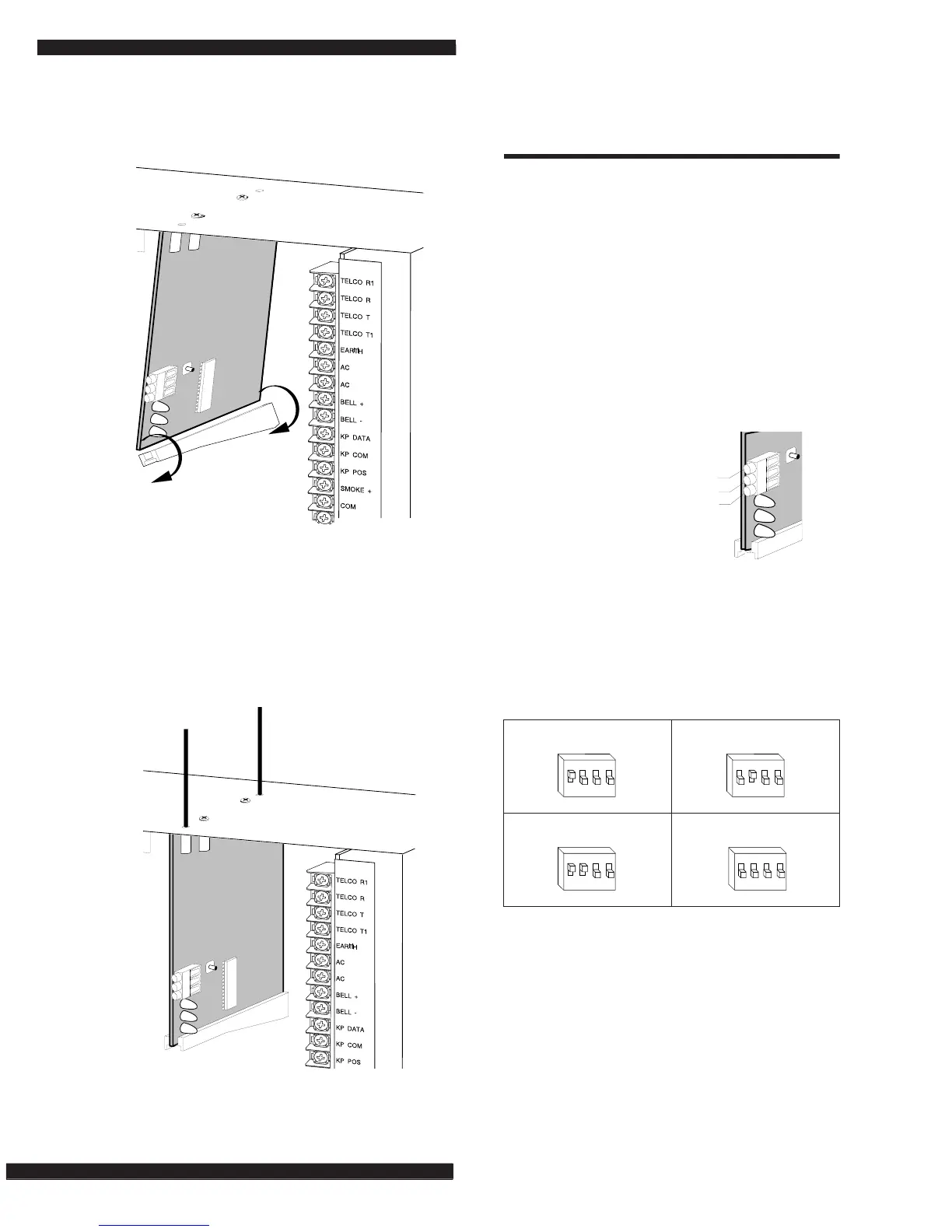
3) Set the module DIP switches to the desired module
number (see Table 1).
4) If using a NX-408 or NX-416, set DIP switch 3 to
enable zone blocks for transmitter learning as follows:
OFF = zones 9-16 or 9-24 enabled for learning
ON = zones 1-8 or 1-16 enabled for learning
9740G04A.DS4
9740G10A.DS4
Table 1. NX Module Number Settings
Module Number 32 Module Number 33
Module Number 34 Module Number 35
9740G14A.DS4
POWER + (TO NX-8 AUX PWR +)
GND (TO NX-8 COM)
DATA (TO NX-8 KP DATA)
ON
1 2
43
EDG
ON
1 2
43
EDG
 Loading...