Do you have a question about the Neve 1084 and is the answer not in the manual?
| Line Input Impedance | 10kΩ |
|---|---|
| Output Impedance | 75Ω |
| Frequency Response | 20Hz - 20kHz ±0.5dB |
| Gain | 80dB |
| EQ Bands | 4-band |
| Low Shelf Frequency | 60Hz |
| Input Impedance | 1.2kΩ |
| Channels | Single |
| Power Supply | +24V, -24V |
| Type | Microphone Preamplifier and Equalizer |
Details on the passive high pass filter design and its termination requirement for optimal response.
Crucial information regarding the 5k1 resistor in the high pass filter circuit and its implications.
Provides rack mount instructions covering ambient temperature, airflow, mechanical loading, circuit overloading, and earthing.
Step-by-step instructions for adjusting the mains voltage setting on the unit.
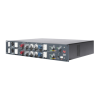
Details on the mains input connectors and switches for 3U and 5U rack units.
Explanation of the red and green LEDs indicating +24V and +48V power status.
Describes the independent output level control, its position in the signal path, and gain reduction.
Guidance on safely handling and transporting modules to prevent damage.
Diagram illustrating the module wiring to an 18-way free plug for standalone units.
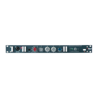
Detailed description of the controls for the 1073 channel amplifier module.
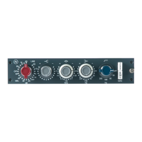
Detailed description of the controls for the 1084 channel amplifier module.
Technical specifications including input impedance, output, distortion, frequency response, and noise.
Recall sheet diagram for the 1073 vertical module controls.
Recall sheet diagram for the 1073 horizontal module controls.
Recall sheet diagram for the 1084 vertical module controls.
Recall sheet diagram for the 1084 horizontal module controls.
Index of schematic drawings for 3U and 5U rack configurations.
Index of schematic and wiring diagrams for the 1073 module and its components.
Index of schematic and wiring diagrams for the 1084 module and its components.