125-MHz Photoreceivers Operation • 9
NEP Characteristics
For Model 1801, the NEP from 0–10 MHz is 3.3 pW
/
and from 10–200 MHz the NEP is 30 pW
/
.
Therefore the integrated noise from 0–130 MHz is
328 nW
rms
and with a conversion gain of 2.4x10
4
V/W,
the expected output noise voltage is 7.8 mV
rms
.
For Model 1811, the NEP from 0–10 MHz is 2.5 pW
/
and from 10–200 MHz the NEP it is 22.5 pW
/
. Therefore the integrated noise from 0–130 MHz
is 246 nW
rms
and with a conversion gain of 2.4x10
4
V/
W, the expected output noise voltage is 5.9 mV
rms
.
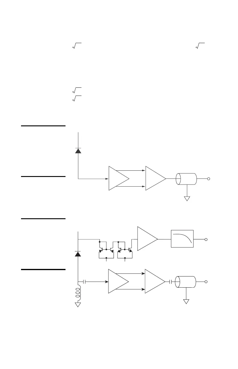
Figure 1:
Functional
block diagram
of Models 1801
& 1811
(DC Versions).
Figure 2:
Functional
block diagram
of Models 1801
& 1811
(AC Versions).
Hz Hz
Hz
Hz
Optical Input
Transimpedance
Amplifier
Compensating
Difference
Amplifier
Output
V
b
G(f)I-V
Compensating
Difference
Amplifier
G(f)
AC-Coupled
Output
I-V
Optical Input
V
-
V
+
I-V
Transimpedance
Amplifier
(low-speed)
Transimpedance
Amplifier
Low-Pass Filter
50 kHz
DC Bias
Monitor
Output
V
b
18X1 HS rcvr rev G.fm Page 9 Thursday, September 20, 2001 2:08 PM
Artisan Scientific - Quality Instrumentation ... Guaranteed | (888) 88-SOURCE | www.artisan-scientific.com