SECTION 35 - HYDRAULIC SYSTEM
35-87
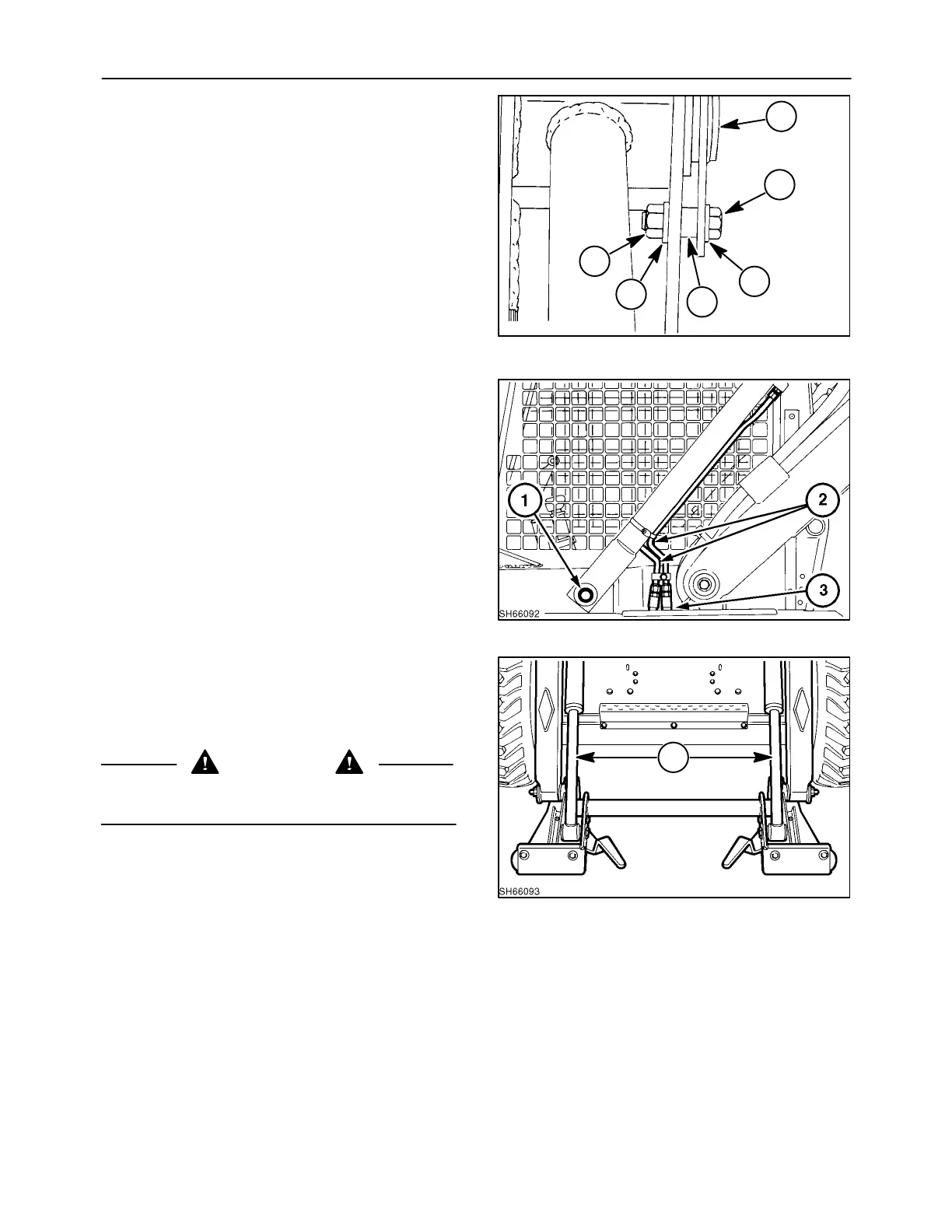
REINSTALLATION
1. Lubricate the boom pivot pins, 1, with an anti-
seize-type lubricant.
2. Install the cylinder onto the loader.
NOTE: Refer to Service Bulletins 5/96 - I6 and 7/96
- I6 for updated pivot pin support information and
proper pin, spacer, and bolt part numbers.
3. Install a 3/8″ bolt, 2; flat washer, 3; and spacer, 4,
through the pivot pin retaining strap and boom
side plate. Secure with flat washer, 5, and lock-
nut, 6.
4. Torque the upper pivot pin hardware to 38 N·m
(28 ft. lbs.).
2
1
19997745
4
3
6
5
152
5. Torque the lower pivot pin hardware, 1, to 338
N·m (250 ft. lbs.).
6. With a six-pound hammer and using a piece of 2
x 4 hardwood to protect the pin, hit the pivot pin
and retaining hardware to properly seat the ta-
pered pin and retorque to 338 N·m (250 ft. lbs.).
7. Reinstall lines, 2, and position to prevent contact
with other components, fenders, etc. at 3.
8. Reinstall the plastic plug into the cap inner shell.
9. Cycle the boom several times to remove the air
from the system and check the cylinder for leaks.
153
BUCKET CYLINDER
Op. 35 710 10
REMOVAL
CAUTION
Never loosen any hydraulic lines without first
relieving all pressure in the system.
1. Remove any attachment, bucket, etc. from the
boom attaching plate and lower the boom to the
lowered position.
2. Extend the cylinders, 1, to the fully extended
position.
3. After stopping the engine and before removing
the seat belt and dismounting from the loader,
turn the ignition switch to the “RUN” position.
4. Push both the boom and bucket pedals to relieve
all residual hydraulic pressure in both circuits.
5. Turn off the ignition switch.
1
154
 Loading...