Do you have a question about the New Holland ts110 and is the answer not in the manual?
This document serves as an Operator's Manual for New Holland TS90, TS100, TS110, and TS115 series tractors, providing essential information for their safe and efficient operation and maintenance. It is an original instruction manual, compliant with Directive 2006/42/EC, Annex I 1.7.4.1.
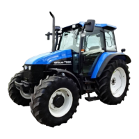
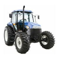
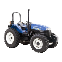
The New Holland TS series tractors are designed for agricultural applications, built to deliver maximum performance, economy, and ease of operation across a wide range of conditions. These tractors are equipped with various systems to facilitate diverse farming tasks. Key operational aspects covered include starting and stopping the engine, managing different transmission types (12x12, 24x24, and 16x16), and utilizing the differential lock and four-wheel drive for enhanced traction.
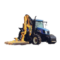
The hydraulic systems are central to the tractor's functionality, with detailed sections on independent power take-off (P.T.O.), top link sensing hydraulics, electronic draft control hydraulics, and remote control valves. These systems enable the tractor to power and control a variety of implements. The three-point linkage, drawbars, and towing attachments are also described, outlining how to connect and use various agricultural tools and trailers.
For operator comfort and control, the manual details the safety frame and cab, seat adjustments, handbrake, foot pedals, and instrument console. Both analogue and analogue/digital instruments, as well as an electronic instrument panel, provide critical information to the operator during use.
The manual emphasizes safe and correct operating procedures. Before starting, operators are instructed to apply the parking brake, place the P.T.O. control in 'OFF', lower the lift control lever, and set remote control valve and transmission levers to neutral. The tractor should only be started and operated from the driver's seat. It is crucial not to bypass neutral start switches for the transmission and P.T.O.
When driving, particular attention is paid to road safety. Operators are advised to consider other road users, pull over to allow traffic to pass, and not exceed legal speed limits. The use of a rotating beacon is recommended for public roads. Proper lighting adjustment is necessary for night driving. Speed reduction before turning or braking is highlighted, with an emphasis on locking brake pedals together for road travel and emergency stops. On four-wheel drive models, the front axle automatically engages for braking at speeds above 8.5 km/h, enhancing braking performance. Extreme caution is advised when towing heavy loads at road speeds.
For downhill driving, maintaining the same gear as for uphill travel is recommended to prevent freewheeling. The differential lock should always be disengaged when turning. Operators must check overhead clearance, especially when transporting the tractor or working near obstacles. Driving with care and at safe speeds is crucial to avoid overturns, particularly on rough ground, when crossing ditches or slopes, and when turning corners. If the tractor becomes stuck or its tires are frozen, reversing out is advised to prevent overturning.
When operating P.T.O.-driven equipment, the P.T.O. must be disengaged, the engine shut off, and the P.T.O. allowed to stop before dismounting or disconnecting equipment. Loose clothing should be avoided near rotating equipment. For stationary P.T.O. operations, the parking brake must be applied, and rear wheels blocked.
The manual outlines a comprehensive maintenance schedule to ensure the tractor's longevity and trouble-free operation. This includes daily checks, and services at 10, 50, 150, 300, 600, 1200 hours (or annually), and 1200 hours (or two years), as well as "as required" maintenance. A lubrication and maintenance chart provides a quick reference for these tasks.
Specific maintenance requirements controlled by warning lights are detailed, guiding operators on how to respond to alerts. The first 50-hour service is particularly important, serving as a factory-recommended check-up after initial use. This service should be performed by a New Holland dealer, and the relevant service report sheets in the manual must be completed and signed by both the operator and the dealer.
Environmental considerations are a significant aspect of maintenance. The manual provides recommendations for the safe storage, use, and disposal of oils, filters, batteries, fuels, antifreeze, and cleaning agents to minimize environmental impact. It advises against burning contaminated fuels or waste oils in ordinary heating systems and stresses the importance of proper disposal for all drained fluids.
Safety during servicing is paramount. The cooling system operates under pressure, so the expansion cap should only be removed slowly after the system has cooled. Open flames must be kept away from the battery and cold weather starting aids to prevent fire or explosion. Servicing the air conditioning system should only be done by specialists due to the risk of frostbite from escaping refrigerant. The engine must be stopped before performing any service.
High-pressure hydraulic fluid and fuel oil in the injection system require extreme caution. Operators are warned not to use hands to check for leaks and to relieve pressure before connecting or disconnecting lines. Medical attention is required immediately if fluid is injected into the skin. Continuous long-term contact with used engine oil can cause skin cancer, so prompt washing with soap and water is recommended. All equipment should be kept clean and properly maintained, and all drained fluids and removed filters disposed of correctly. Tractor wheels are heavy and must be handled and stored carefully to prevent injury.
The manual also includes important information on product identification, with locations for the vehicle identification plate, cab/frame identification, and tractor serial numbers. This information is crucial for ordering parts, requesting service, and identifying the tractor if stolen. The use of genuine parts is strongly recommended to maintain the tractor's design characteristics and safety. Unauthorized modifications are prohibited.
| Engine Power | 110 hp |
|---|---|
| Cylinders | 6 |
| PTO Speed | 540/1000 RPM |
| Hydraulics Type | Open center |
| Engine Type | Diesel |
| Hydraulic Remotes | 3 |
| Hydraulic Flow | 18.5 gpm |
| Hydraulic Pump Flow | 18.5 gpm |