EasyManua.ls Logo

New Holland TS-125A User Manual

New Holland TS-125A
154 pages
To Next Page IconTo Next Page
Page #1 background imageLoading...
Page #1 background image
Published 01-05 Part No. 02982279
ASSEMBLY MANUAL
BOOM ARM MOWER
© 2005 Alamo Group Inc.
ALAMO INDUSTRIAL
1502 E. Walnut
Seguin, Texas 78155
210-379-1480
Assembly Instruction Manual
New Holland - Cab 2 WD / 4 WD
TS-100A, TS-115A, TS-125A, TS-135A
Tractors equipped with additional options, special equipment, tractor manufacturer modifications,
new tractor models, or Customer alterations may prevent this Mount Kit from being properly
mounted to the tractor. Alamo Group is not responsible for modifications to the MountKit to
accommodate these differences.
Question and Answer IconNeed help?

Do you have a question about the New Holland TS-125A and is the answer not in the manual?

New Holland TS-125A Specifications

General IconGeneral
TypeTractor
Engine Power125 hp
Engine TypeDiesel
FuelDiesel
Cylinders4
Displacement4.5 L
Transmission Gears16 forward and 16 reverse
PTO Power110 hp
PTO Speed540/1000 rpm

Summary

ASSEMBLY MANUAL

Section 1 - Model Specifications

Maverick Boom 24' & 30'

Details specifications for the 24 and 30 foot Maverick boom models.

SPECIFICATIONS - MAVERICK

READ THIS BEFORE BEGINNING ASSEMBLY, REPAIRS OR TESTING:

Crucial precautions regarding the Maverick's computerized electronics.

11. TORQUE VALUES - BOLTS:

Recommended torque specifications for various bolts used in assembly.

Section 2 - Maverick Boom

Tractor Preperations

Steps required to prepare the tractor before attaching the boom.

General Information / Installation Requirements

WARNING!

Critical safety warnings related to component handling and tractor operation.

Section 3 MAVERICK

Pump & Driveshaft Installation

Details the process for installing the pump and driveshaft assembly.

Pump / Drive Assembly Instructions

Installing Pump, Pump Drive Components and Hydraulic Tank:

Covers the initial installation of the pump, drive components, and hydraulic tank.

Section 4 MAVERICK

Hydraulic Tank & Control Valve Installation

Detailed steps for installing the hydraulic tank and control valve assembly.

Hydraulic Tank & Control Valve Installation

Install Hydraulic Tank to Front of Tractor:

Steps for mounting the hydraulic tank and valve assembly to the tractor.

Section 5 Maverick Boom

Battery Modification

Procedures for modifying the tractor's battery location for boom installation.

Frame Installation

Under Mount Frame Asy:

Details the assembly of the under-mount frame structure.

Counter Weight Installation 24 & 30 Foot Boom:

Procedures for installing counterweights for both boom sizes.

Turret Assembly Installation 24 & 30 Foot Boom:

Steps for mounting the turret assembly onto the frame.

Frame Installation:

Section 6 MAVERICK

Optional RH Lexan Door Installation

Instructions for installing the optional right-hand Lexan door.

Section 7 MAVERICK

Standard Wheel Weight & Auxiliary Wheel Weight Installation

Procedures for installing wheel weights for improved tractor stability.

Section 8 MAVERICK

Joystick - Wire Harness & Valve Installation

Guide for installing the joystick, wire harness, and valve assembly.

Joystick / Electrical Mounting

Installing Wiring Harness and Joystick:

Detailed steps for routing and connecting the wiring harness and joystick.

Section 9 MAVERICK

Boom & Head Installation

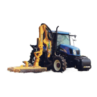
Detailed steps for installing the boom and mower head assembly.

Boom / Head Installation

Boom Installation / Boom Hoses:

Covers the installation of the boom assembly and its associated hydraulic hoses.

Lower Boom onto Turret Assembly.

Instructions for carefully lowering the boom onto the turret assembly.

Connect Hose From Boom to Control Valve.

Steps for connecting hydraulic hoses from the boom to the control valve.

Routing Cylinder Hoses from Boom to Valve

Details the routing of cylinder hoses from the boom to the control valve.

Routing Boom Hoses to Pump

Details the routing of boom hoses to the tractor's pump.

Section 10 MAVERICK

Fill Oil Tank Electronic Controls Setting

Guide for filling the hydraulic oil tank and setting electronic controls.

Hydraulic Oil Installation 2 WD & 4 WD

Hydraulic Tank Filling:

Procedures for filling the hydraulic tank with the correct oil type and level.

Prime Hydraulic Pump:

Instructions for priming the hydraulic pump before system operation.

CONTROL VALVE - BOOM & MOTOR CONTROL

Maverick Boom and Motor Control Circuits:

Overview of the boom and motor control circuits and system operation.

CONTROL VALVE - BOOM CONTROL

CONTROL VALVE - ELECTRONIC NETWORK

CONTROL VALVE - INSTRUMENTATION

CONTROL VALVE - JOYSTICK

Adjust Boom Swing Stop

Boom Swing Adjustment:

Instructions for adjusting the boom swing stop to prevent cab damage.

Section 11 MAVERICK

Mounting Specifications

Provides specifications for mounting the Maverick boom to specific tractor models.

Mounting Specifications

Mounting Component ID 24 ft. Cab & 2wd

Mounting Component ID 24 ft. Cab & 4wd

Mounting Component ID 30 ft. Cab & 4wd

Section 12 MAVERICK

PRE-DELIVERY INSPECTION CHECKLIST

A checklist for pre-delivery inspection of the assembled unit.

MAVERICK PRE-DELIVERY INSPECTION CHECKLIST

Related product manuals