Do you have a question about the New Holland TS-115A and is the answer not in the manual?
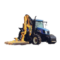
Provides assembly instructions for the Maverick Boom Arm Mower on specified New Holland tractor models.
Crucial safety and handling precautions for the Maverick unit, especially regarding electronics.
Safety warning to disconnect the battery terminal before working on electrical systems.
Safety warning regarding the use of overhead cranes and proper lifting procedures.
Specifies required personal protective equipment (PPE) for safe assembly operations.
Safety instructions to ensure the tractor engine is off and secured before assembly.
Critical safety warning about properly blocking and supporting the tractor before moving tires.
Safety advice on handling heavy mower components using appropriate equipment.
Safety precautions for handling heavy tractor tires to prevent injury.
Warning about the dangers of high-pressure hydraulic oil leaks and proper leak checking.
Details on preparing the tractor by adjusting wheel spacing and removing specific components.
Critical warning against welding near electronic components without proper precautions.
Instructions for installing the pump and driveshaft assembly onto the tractor.
Covers the installation of pump drive components, the pump assembly, and the hydraulic tank.
Instructions for installing the driveshaft half with the flange yoke, ensuring proper timing.
Instructions for connecting the driveline half to the pump, ensuring correct timing and alignment.
Steps for installing the pump onto its mount weldment, including alignment and tightening.
Instructions for installing the hydraulic tank and the control valve assembly.
Steps for mounting the hydraulic tank and control valve assembly to the front of the tractor.
Procedure for lifting and mounting the assembled hydraulic tank and control valve.
Steps for installing the main frame components that connect the boom assembly to the tractor.
Explains the need to relocate the battery holder and the kit provided for this purpose.
Procedure for relocating the tractor's exhaust system to ensure clearance.
Instructions for replacing the tractor's fuel tank and its associated components.
General overview and preparatory steps for installing the under-mount frame assembly.
Diagram showing the components of the under-mount frame assembly and their labels.
Instructions for installing the frame components, emphasizing correct orientation and bolt usage.
Steps for installing the left and right rear frame mount rails, including stabilizer bracket connections.
Instructions for installing the left and right front frame mount rails, noting their orientation.
Procedure for installing the center frame weldment, ensuring correct bolt usage and washer placement.
Instructions for installing the boom rest weldment, noting differences for 24ft and 30ft booms.
Details on installing counterweights for both 24-foot and 30-foot boom models for stability.
Instructions for installing the turret assembly onto the tractor's frame.
Instructions for installing the front axle stabilizer kit, including bracket and cylinder connections.
Instructions for installing the optional right-hand Lexan door onto the tractor cab.
Steps for safely removing the factory glass door and its components.
Final steps for installing the new Lexan door, including hinge alignment and tightening.
Instructions for filling the left rear tractor wheel with a liquid mixture for added weight.
Steps for installing the 1400 lb wheel weight onto the tractor's rear wheel.
Instructions for installing the auxiliary wheel weight kit, consisting of three steel plates.
Covers the initial steps for installing the wiring harness and joystick assembly.
Covers the initial steps for installing the wiring harness and joystick assembly.
Procedure for replacing the factory arm rest with a specialized mount for controls.
Guidance on using wiring harness schematics to connect interior and exterior harnesses.
Schematic showing connections for CAN modules, display, and E-Stop switch.
Schematic detailing the exterior wire harness connections to various tractor and implement components.
Instructions for installing the boom and mower head assembly onto the tractor.
Details on connecting boom hoses to the turret assembly and routing them.
Instructions for connecting the boom lift cylinder and its hoses.
Steps for lowering the boom onto the turret assembly and securing it with mounting pins.
Procedure for connecting the lower end of the lift cylinder to the boom mount.
Instructions for connecting the mower head to the boom using mounting pins.
Instructions for connecting cylinder hoses from the boom to the tractor's control valve and diverter valve.
Diagram illustrating the hydraulic schematic for the boom and control valve connections.
Detailed instructions on routing cylinder hoses from the boom to the control valve and diverter valve.
Instructions for routing boom hoses to the tractor's pump, including specific hose details.
Guidance on routing pump hoses at the tank, referring to figures for correct locations.
Diagram illustrating the correct routing of hydraulic hoses for the tank connections.
List and description of hoses connecting the motor and boom pump.
Instructions for filling the hydraulic oil tank with the correct type and grade of oil.
Procedure for setting up and configuring the electronic control system for the boom and mower.
| Engine Power | 115 hp |
|---|---|
| Cylinders | 6 |
| Displacement | 6.7L |
| PTO Speed | 540/1000 rpm |
| Hydraulic Flow | 18.5 gpm |
| Rated RPM | 2200 |
| Rear tire size | 18.4 R34 |
| Fuel | Diesel |
| Type | Agricultural Tractor |






 Loading...