© 2021 Copyright Newmar Corporation. All rights reserved. For the most up-to-date version of this content, and for more product-specific information, please refer to Newgle.
65
ELECTRICAL
The factory default value for the Search feature is 5
watts. It can be turned o or adjusted from 5 to 50
watts using a remote control display.
IMPORTANT
!
SEARCHING
When the inverter is first turned on, the automatic Search
feature is enabled. This feature conserves battery power
when AC power is not required. In this mode, the inverter
pulses the AC output looking for an AC load (i.e., electrical
appliance). Whenever an AC load (greater than 5 watts)
is turned on, the inverter recognizes the need for power
and automatically starts inverting. When there is no load
(or less than 5 watts) detected, the inverter automatically
goes back into Search mode to minimize energy
consumption from the battery bank. When the inverter is
searching, the inverter’s green LED fl ashes (medium flash
– blinks once every second).
INVERTING
When a load greater than 5 watts is connected to the
inverter output, the MS Series inverts the DC power
from the battery and supplies 120 VAC power to your
sub-panel. The inverter’s green LED fl ashes once every
second (medium flash) to indicate it is inverting. The
amount of time the inverter can be inverting and providing
power is directly related to the amount of AC loads that
are connected, and the capacity of the battery bank.
Standby Mode
The MS Series features an internal battery charger and an
automatic transfer relay when operating in Standby mode.
Standby mode begins whenever AC power (utility or
generator) is connected to the inverter’s AC input. Once
the AC voltage and frequency of the incoming AC power
is within the AC input limits, an automatic AC transfer
relay is activated. This transfer relay passes the incoming
AC power through the inverter to power the AC loads on
the inverter’s output. This incoming power is also used to
activate a powerful internal battery charger to keep the
battery bank charged in case of power failure.
BULK CHARGING
This is the initial stage of charging. While bulk charging,
the charger supplies the battery with controlled constant
current. The charger remains in bulk charge until the
absorption charge voltage is achieved. The inverter’s
green LED stays ON (solid) to indicate bulk charging.
FLOAT CHARGING
The third charging stage occurs at the end of the absorb
charging time. While float charging, the charge voltage
is reduced to the float charge voltage. In this stage, the
batteries are kept fully charged and ready if needed by
the inverter. The inverter’s green LED flashes once every
8 seconds (slow flash) to indicate fl oat charging. The
Float Charging stage reduces battery gassing, minimizes
watering requirements (for flooded batteries), and ensures
the batteries are maintained at optimum capacity.
ABSORB CHARGING
This is the second charging stage and begins after the
absorb voltage has been reached. Absorb charging
provides the batteries with a constant voltage and
reduces the DC charging current in order to maintain the
absorb voltage setting. The inverter’s green LED fl ashes
once every second (medium flash) to indicate absorption
charging for 2 hours, then switches to float charging.
Battery Charging
The Charge mode provides up to four separate charging
stages: Bulk Charging, Absorb Charging, Float Charging
and Full Charge.
FULL CHARGE (BATTERY SAVER™
MODE)
The fourth stage occurs after four hours in the Float
Charging stage. The Full Charge stage is designed to
keep batteries fully charged over long periods, and to
prevent excessive loss of water in flooded batteries or
drying out of GEL/AGM batteries. In this stage, the charger
is turned o and begins monitoring the battery voltage; if
the battery voltage drops low (12.7 VDC or less on 12-volt
Models), the charger automatically initiates another four
hours in float charge.
OFF
Indicates the inverter is o: There is no AC power
(inverter, utility, or generator) at the inverter’s output
terminals. If the LED stays o after pressing the ON/OFF
switch, there is a fault condition (such as low battery, high
battery, overload, over-temperature or an internal fault).
Refer to the Troubleshooting section of Magnum’s owner’s
manual to help diagnose/clear any fault condition.
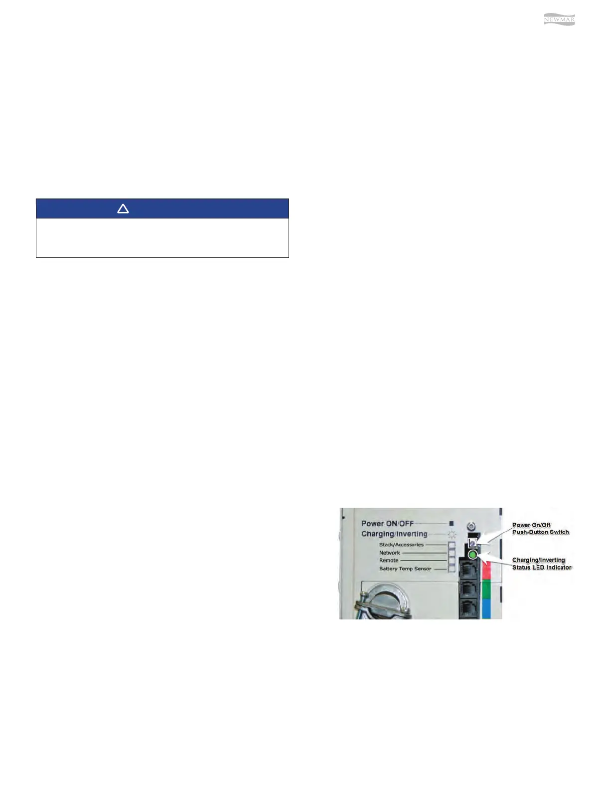
Status LED Indicator
The status indicator is a green LED (Light Emitting Diode)
that provides information on the operational mode of the
inverter. Watch this indicator for at least 10 seconds to
determine the inverter’s operational condition from the
information below: