© 2021 Copyright Newmar Corporation. All rights reserved. For the most up-to-date version of this content, and for more product-specific information, please refer to Newgle.
76
ELECTRICAL
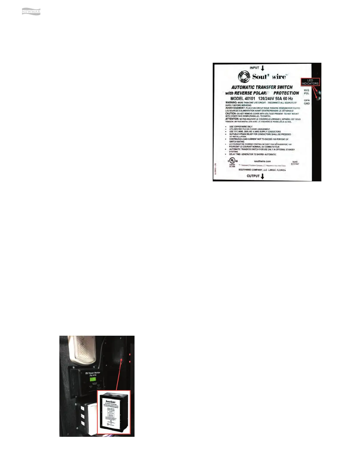
Southwire 50 Amp Automatic Transfer Switch (Model:
40101-001)
Source(s): Southwire Automatic Transfer Switch Troubleshooting Guide
(Models 40100, 40101, 40140, 41300, 41301)
Product(s): Southwire 50 Amp Automatic Transfer Switch (Model: 40101,
Newmar Part Number: 157536)
This article provides basic operation instructions for a Southwire 50 Amp Automatic Transfer Switch (Model: 40101).
Testing Operation
Plug the shore power cord into a good shore power
source and, after a short delay, shore power should be
transferred through and available for use. If the generator
is started after approximately 40 seconds, the transfer
switch should transfer power from shore power to
generator power. Turn the generator o and, after a short
delay, the transfer switch should switch back to the shore
power. (Source: Doc 505-00175a)
This transfer switch has two visual indicators designed to
give the user a quick indication of power conditions that
need to be corrected before using the coach.
Open Ground Indicator Illuminated: Unplug shore power.
Use a voltmeter to check ground and neutral. Voltage
should read -0-. If not, finding another power source is
recommended.
Reverse Polarity Indicator Illuminated: Unplug shore
power. Use a voltmeter to check ground and neutral.
Voltage should read -0-. If not, finding another power
source is recommended.
Southwire 50 Amp Automatic Transfer Switch (Model:
40450RVC)
This article provides basic operation instructions for a Southwire Surge Guard 50 Amp Automatic Transfer Switch (Model:
40450RVC).
The 40450 series automatic transfer switch (ATS) has
many dierent protective features to protect your coach
from low quality power. Included in these are protection
against high voltage, low voltage, and an incorrectly
connected chassis ground. If one of these fault conditions
is encountered, the ATS will open both contactors in order
to protect the coach. Once the fault condition goes away,
the ATS will delay for approximately 2.5 minutes before
trying to close the appropriate contactor again.
A remote power monitor may be installed in select
coaches and allows for continuous visual indication of
source voltage and load current or diagnostics.
If the ATS fails to close the contactor or transfer when
expected, check the 40450 display to see if an error
message is displayed. The screen will flash an error
message for that failure such as “Loss of Ground”, “High
Volt”, or “Reverse Polarity”. The error condition must
be corrected in order for the transfer switch to function
correctly. Refer to the table on the following page for help
in troubleshooting these conditions.
If there is no error message and the display instead reads
“Delay Active” this means that the fault condition has
cleared and that the switch is going through a 2.5 minute
delay before it will attempt to close the contactor again.
Wait until this delay is over to see if the ATS correctly
closes its contactor.
If no display is available, check the level of the input
voltage to ensure it is within the proper operating limits.
Also check that the ATS is correctly connected to chassis
ground and that the neutral conductor is correctly
connected to ground at the power pedestal. Wait 2.5
minutes to check if the fault condition was temporary and
has cleared. If so, the contactor will pull in at the end of
the 2.5 minute period.