© 2021 Copyright Newmar Corporation. All rights reserved. For the most up-to-date version of this content, and for more product-specific information, please refer to Newgle.
68
ELECTRICAL
LCD DISPLAY
The LCD display is used for setting up the system
operation, as well as viewing the current operating
status and fault conditions. This display has two lines of
alphanumeric characters and features a backlight that can
be set to turn o to conserve power.
The top line provides the inverter/charger status, which
is detailed in this section. The bottom line displays
battery information while using the METER menu, system
troubleshooting information while in the TECH menu,
and displays menu items that can be configured for your
specific system operation when using the SETUP menu.
This display automatically powers-up with the current
system status on the top line and the home screen
(detailing the inverter’s DC voltage and current) on the
bottom line.
LED INDICATORS
There are four LED indicators on the front panel that light
solid or blink to indicate the inverter/charger’s status. When
the remote is first powered-up, all the LEDs come on as it
goes through a self-test. Once the self-test is complete, the
LEDs along with the LCD provide the operating status of
the inverter/charger.
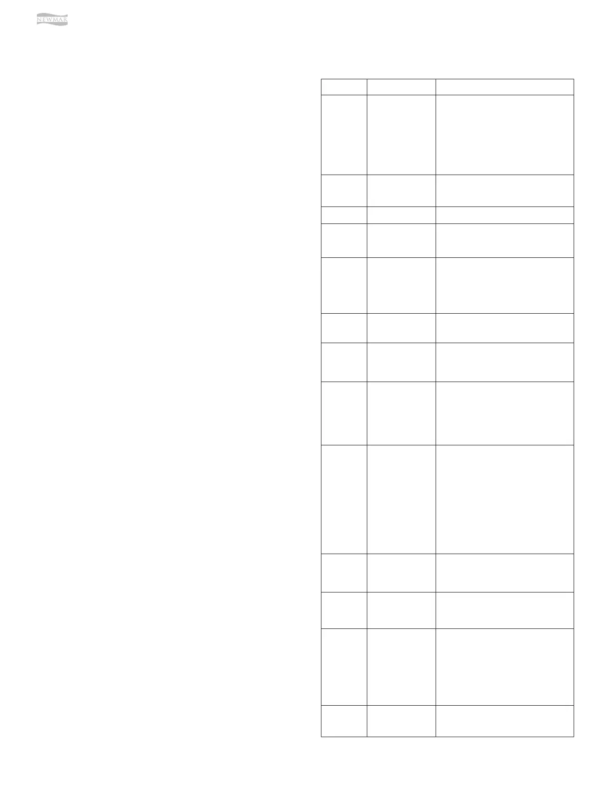
LED Status Meaning
PWR
(Green)
OFF
1. Inverter is disabled;
2. Remote is in Power Saver mode -
press any button to activate LEDs;
3. No power to remote (check remote
cable or power to inverter); or,
4. No AC power at the inverter’s AC
output terminals.
PWR
(Green)
ON
AC power is available from inverter, shore,
or generator at the inverter’s AC output
terminals.
FAULT (Red) OFF Normal operation.
FAULT (Red) ON
A fault condition has been detected.
Check the LCD display to find and correct
the cause.
CHG
(Green)
OFF
1. Remote is in Power Saver mode –
press any button to activate LEDs; or,
2. Charger o – no utility or AC
generator present.
CHG
(Green)
ON
Bulk, Absorb, Float, or Equalize Charge
mode (see LCD display to determine
charge status).
CHG
(Green)
BLINKING, display
says
“Charger Standby”
The charger is in Charger Standby mode.
This occurs when the ON/OFF CHARGER
button is pressed to disable the charger.
CHG
(Green)
BLINKING, display
says “Full Charge”
or “Silent”
The charger is in Battery Saver mode.
This mode monitors battery voltage level
and only charges if the battery voltage
decreases to a low level. Silent mode will
automatically start charging when the
Rebulk setting is reached.
CHG
(Green)
BLINKING, display
says Charging
status (i.e., Bulk,
Absorb, Float)
The charger current is automatically
decreased because:
1. Charger Back-o – the inverter’s
internal temperature is getting hot,
current is decreased to reduce/
maintain temperature; or,
2. Low AC Input Voltage – the input AC
voltage is low, charger is disabled to
help stabilize incoming AC voltage to
prevent AC disconnect.
CHG
(Green)
BLINKING, display
does not
show any charge
status
The inverter is detecting AC voltage (from
utility or an AC generator) on the inverter’s
AC input terminals.
INV (Green) OFF
1. Inverter disabled; or,
2. Remote in Power Saver mode – press
any button to activate LEDs.
INV (Green) ON
Inverter is enabled:
1. Supplying AC power on the output; or,
2. In Inverter Standby (if both INV and
CHG LEDs are on); the inverter will
automatically supply AC power to the
loads if shore or generator power
is lost.
INV (Green) BLINKING
Inverter is in Search mode (the AC load is
below the SETUP menu’s 01 Search Watts
setting).
LED INDICATOR GUIDE
Use the LEDs along with the LCD display to determine the
operating status.
ON/OFF PUSH BUTTONS
•
ON/OFF INVERTER – This button toggles the inverter
function on and o. The green INV LED turns on and
o with the button.
• ON/OFF CHARGER – This button toggles the charger
function on and o whenever the charger is actively
charging. The green CHG LED turns on and o with
the button. This button is also used to initiate an
Equalize charge.
MENU BUTTONS
These five buttons provide quick access to menu
items that can help with configuring, monitoring and
troubleshooting your inverter/charger system.
• SHORE – This button allows you to set the appropriate
breaker size for the incoming utility/shore power and
is used to control the amount of AC amps the battery
charger uses from the HOT 1 IN input.
• AGS – This button allows the networked Auto
Generator Start (MEAGS-N) controller to be configured
to specific system preferences and enables you to
check the AGS’s status (when connected).
• METER – This button provides meter information on
the inverter/charger system.
• SETUP – This button allows the inverter/charger to be
configured to your specific system preferences.
• TECH – This button allows you to access menu
selections that can help service personnel with
troubleshooting and also allows the factory default
setting to be restored.