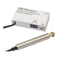
4 Specifications
Dimensions
(L x W x H including standoffs)
3.75 in x 2.53 in x 1.26 in
95 mm x 64 mm x 32 mm
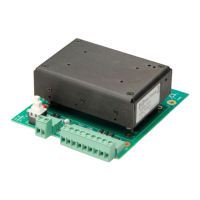
2.2 Model 8712 pin Descriptions
1
SYSTEM
GROUND
Power return
2 +V IN Input power, 10–16 V
3 +V IN Input power, 10–16 V (same as pin 2)
4
SYSTEM
GROUND
Power return (same as pin 1)
5
SYSTEM
GROUND
Power return (same as pin 1)
6
SYSTEM
GROUND
Power return (same as pin 1)
7 +5V OUT
Logic-supply output connected to a 1-kΩ resistor. Used for
manufacturing test and mode configuration. Typical output voltage
range is 4.8 to 5.2Volts DC (no load).
8 ANALOG IN– Voltage-controlled rate input. Connect to analog common.
9 ANALOG IN+
Voltage-controlled rate input. Connecting to analog voltage ±10 V
gives full-scale rate of 2 kHz. The input impedance is 14.1 kΩ to
ground. Enabled by MODE 0,1 or 1,1 inputs.
10 DGROUND Opto-coupler return. Connect to digital ground close to control logic.
11 DIR+/A
Opto-coupled TTL control input enabled by MODE 0,0 or 1,0 inputs.
In Step/Direction mode, controls direction: high=clockwise,
low=counterclockwise. In Quadrature mode, acts as quadrature A.
12
PULSE+/B
Opto-coupled TTL control input enabled by MODE 0,0 or 1,0 inputs.
In Step/Direction mode, each falling edge initiates a step. In
Quadrature mode, acts as quadrature B.
 Loading...