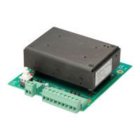
22 Model 8703 System
Rounding to the nearest 10% value, 1.2 kΩ,
Therefore the 0603 package is can be used in this application.
For 12V logic,
Rounding to the nearest 10% value, R=2.7 kΩ,
So the 0603 package is marginal and you should use 0805.
4.1.9 Temperature Sensor
Pin 8 is connected to the 8712 temperature sensor output. The output
impedance is 100 kΩ, so use a high impedance input to monitor this
terminal. See Figure 4 for a typical voltage vs. temperature plot. The
thermistor used in the 8712 temperature sensing circuit has a ±10% tolerance.
C100 is connected across Pins 8 and 9 to improve noise filtering. TVS diode
D106 is connected across Pins 8 and 9 to attenuate voltage spikes. D106 is
not needed if short wires are used to connect Pins 8 and 9 to the input of the
voltage measuring circuit.
Pin 9 is the ground reference for the temperature sensor.
4.2 Picomotor Connections
For the convenience of your application, the Model 8703 system board
provides two connectors, J102 and J103, to connect the 8703 Drive Module
to the Picomotor.
J103 has 3 screw terminals for connection to the Picomotor wires and an
optional cable shield.
Terminal Name Description
1 FRAME GROUND
Return for EMI T-filter on PULSE
RETURN and PULSE OUTPUT.
2 PULSE OUTPUT Drive pulse.
3 PULSE RETURN Drive pulse return.

 Loading...