based on multiple events. For example, during a single trajectory of motion, the
XPS allows sending TTL trigger outputs at the motion start, constant velocity
start, constant velocity end and the motion end as well as at any trajectory
elements defined for specific position and velocity values.
Implementation of TTL input and output in the XPS controller can be done
similar to IF/THEN statements in programming. “If” the event occurs, “then”
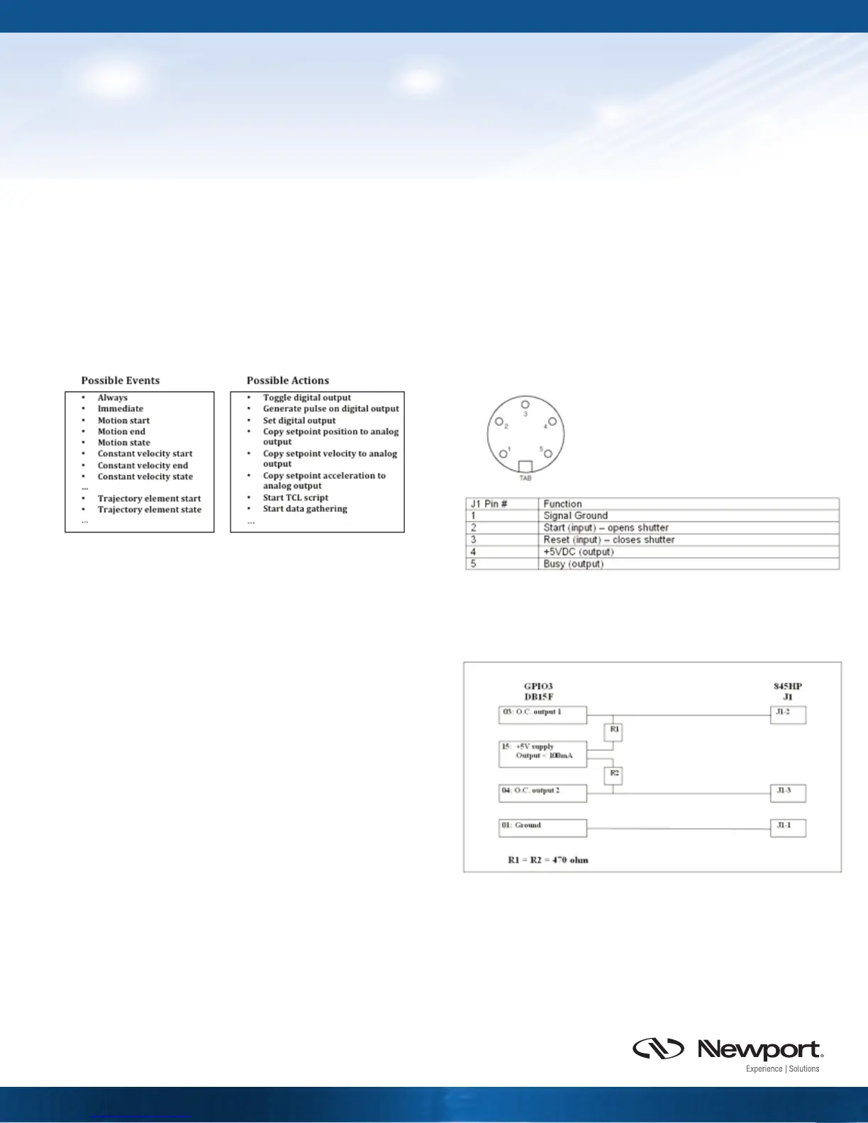
the action is triggered. Some of the available events and actions are shown in
Figure 4.
When the XPS is triggered by other instruments, a trigger signal from other
instruments is always defined as the event. Number of actions can be
triggered such as executing specific motion commands, gathering data,
sending modulated analog output signals or starting a programmed trajectory.
When the XPS triggers other instruments, the triggering events can be defined
based on time, specific motion parameters (velocity, acceleration, deceleration,
start or stop), state of motion or a trajectory. In this case, the action is always
the triggering signal to other instruments.
Synchronization Time Delay and Position Error
Typical delay of sending out the trigger signal from the XPS controller is 100
μs, coming from a servo cycle of the controller electronics. While a ‘time’
based event triggers an action immediately every servo cycle of 100 μs, an
event related to ‘motion’ triggers an action based on the motion profiler, which
runs on every 400 μs.
For applications demanding high accuracy and fast synchronization to external
devices, the XPS controller features ‘Position Compare Output’ (PCO), providing
50 ns delay between the moment of crossing specific positions and sending
out the trigger signal. Similarly, the ‘Trig In’ connector of the XPS enables 50 ns
delay between a trigger input signal and an acquisition of position data.
Trigger Synchronization using a
Newport XPS Series Motion Controller
TECHNICAL NOTE
A minimum latency in the trigger delay is critical in high speed, high
throughput motion where the trigger output signal is sent on the fly during a
move. With 50 ns latency of the trigger pulse from PCO, the scanning speed of
200 mm/s from a motorized stage produces minimal uncertainty of 10 nm in
position, which is much smaller compared to uncertainty of 20 μm resulting
from 100 μs latency of trigger pulse from the GPIO.
Example #1: Digital TTL Output to Trigger a Mechanical Shutter
In the following example, a Newport 845HP digital shutter system is triggered
by digital TTL outputs from the GPIO3 connector of an XPS-Q4 universal
controller.
The digital TTL outputs from GPIO3 connector are pulled up to +5V supply with
resistors, as shown in Figure 6.
Please note that the inputs of 845HP interface connector are “active high” and
the digital outputs of the GPIO are in negative logic. This means that the
shutter will open with high-to-low transition of the trigger pulse to J1-2 pin,
and close with the high-to-low transition of the trigger pulse to J1-3 pin.
Figure 4: Possible Events and Actions from XPS controller
Figure 5: Description of 845HP shutter interface control 5-PIN DIN connector
Figure 6: Wiring diagram of GPIO3 to 845HP J2 interface connector
 Loading...


