ENG
220~240V AC OPERATED
PHOTOELECTRIC SMOKE ALARM
MODEL: GNS-2236/RF
(With 9V Battery Back-up)
15
0086-CPR-632447
Nexa13546-CPR-632447
EN14604:2005/AC:2008
Nexa Trading AB, Box 12200, 40242 Gothenburg
Sweden
Fire Safety and installed in buildings
Main Features :
Photoelectric Sensor For Slow
Smoldering Fires
Power / Alarm indicator
HUSH FEATURE
Battery Back Up
Low Battery Warning
Wireless interconnectable (Up To 20
smoke And/Or heat Alarms)
Dip switch for coding
Supplied with Fixing Kit
Loud 85dB Alarm Signal
Dust cover
This instruction leaflet contains important
information on the correct installation and operation
of your heat alarm. Read this leaflet fully before
attempting installation and retain for future
reference.
SPECIFICATION
Power Source : 220-240Vac~ 50-60Hz with
9V battery back-up (battery
included)
Battery Back-up : 9V Alkaline Battery (Gold Peak
1604A, Energizer 522, Duracell
MN1604)
Battery Back-up Life : In the event of a break in the
mains supply the battery will give
detector operation for one month
minimum
Operation Current : <40mA operation (In Alarm)
Transmit & Receive frequency: 868.4MHz
Digital modulation method: GFSK
Transmitting & Receiving distance: over 80M in open space
Transmit data rate : 50Kbps
Coding selection : 16 combinations
Max. wireless interconnection: 20 units
Max. wire interconnection : 40 units
Sensitivity to smoke : 0.65-1.52 % per foot obscuration
Operation Temperature : 0
o
C-40
o
C
Ambient Humidity : 10%-90%
Alarm Sound Level : 85 Decibels at 3 metres
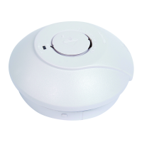
PRODUCT DESCRIPTION
GNS-2236/RF is a multiple station photoelectric smoke alarm
with a radio link mounting base which allows it to be
interconnected to other Nexa alarms. (Can be mixed and
matched with the NEXA Photoelectric Smoke Alarm GNS-
2236/RF and MTS-166/RF) The radio link base has both signal
transmitter and receiver built-in. It transmits a Radio
Frequency(RF) alarm signal when the unit detects smoke. When
it receives an RF alarm signal from other unit, it will sound. This
interconnect feature allow up to 20 units to be interconnected
together within 100 meters and thus all alarms will sound when
any one is activated. Using the wireless signal transmission
technology awards wiring location problem and allows the
smoke and heat alarms to be placed futher apart when
compared to a wired installation.
Note: This smoke alarm cannot be connected to any other
device such as a fire alarm panel.
All the Smoke Alarms should be interconnected to ensure the
early warning will be heard, particularly by somebody sleeping. A
properly designed early warning fire system ensures the alarm is
given before the escape routes become blocked with smoke.
LOCATING THE SMOKE ALARM
If your dwelling is on a single storey, for minimum protection
you should fit an alarm in a corridor or hallway between the
sleeping and living areas (incl. Kitchens). Place it as near to
the living areas as possible and ensure the audible alarm can
be heard when the bedrooms are occupied. See Figure 1 for
examples.
If your dwelling is multi-storey, for minimum protection one
alarm should be fitted at the bottom of the staircase with further
alarms fitted on each upstairs landing. This includes
basements but excludes crawl spaces and unfinished attics.
See Figure 2 for examples.
NOTE: For maximum protection an alarm should be fitted in
every room (except kitchen, bathroom and garage).
DO NOT FIT AN ALARM IN THE KITCHEN OR BATHROOM,
as cooking fumes or steam may trigger the alarm.
DO NOT FIT ALARM IN GARAGE, as exhaust fumes are likely
to set it off.
POSITIONING THE SMOKE ALARM
Ceiling Mounting
As hot smoke rises and spread out, it is advisable to mount on
a ceiling in a central position. Avoid areas where there is no air
circulation. E.g. Corners of rooms and keep away from items
which may prevent the free flow of air. Place the unit at least
300 mm from and light fitting or decorative object which might
obstruct smoke entering the alarm. Keep at least 300 mm away
from walls. See Figure 3i.
Wall Mounting
Do not mount tight into the corners. Put the top edge of your
smoke alarm between 150 and 300mm below the ceiling. Keep
at least 300mm from room corners. See Figure 3i
On a Sloping Ceiling
In areas with sloping or peaked ceilings install your Smoke
Alarm 900mm from the highest point measured horizontally
because “dead air” at the apex may prevent smoke from
reaching the unit. See Figure 3ii.
Areas to be avoided include the following :
Situations where the temperature may fall below 0
o
C or
rise above 40
o
C
Humid areas such as bathrooms, kitchens, shower
rooms where the relative humidity may exceed 90%
Near a decorative object, door, light fitting, window
molding etc., that may prevent smoke from entering the
alarm.
Fume filled environments such as garages. Exhaust
gases may cause false alarms.
Adjacent to or directly above hot components such as
radiators or wall vents that can effect the direction of air
currents.
In very dusty or dirty environments such as workshops.
Locate unit at least 1.5m and route wiring at least 1m away
for fluorescent light fittings as electrical “noise” and/or
flickering may affect the unit. Do not wire into the same circuit
as fluorescent lights or dimmers.
Do not locate in insect infested areas. Insects and
contamination on the alarm sensor can increase its response
time.
INSTALLING THE SMOKE ALARM
WARNING – This smoke alarm is mains powered and requires
wiring by a qualified electrician in accordance with the current
IEE Regulations for Electrical Installations (BS7671).
The circuit used to power the smoke alarm must be a dedicated
permanent supply that cannot be switched off accidentally by
the normal user. Before installing ensure the electrical supply
is isolated.
WARNING: To prevent injury, this smoke alarm must be
securely attached to the ceiling/wall in accordance with the
installation instructions.
All handwired interconnect smoke alarms must be supplied from a
single power circuit and a common neutral must be used.
WARNING:Do not connect the interconnect wire to Live or
Neutral.
Disconnect the AC main power from the circuit that is going to
be used.
Having established the mounting location install a junction
box suitable for locating the termination point. Ensure that
there is no other electrical wiring or pipe work in the area
adjacent to the mounting surface.
Unlock the detector unit from the base by pushing up the
temporary latch with a screw driver. See Figure 4
Set the coding. Each unit comes a four positions dip
switch(see Figure 6) for coding the transmit and receive
frequency to prevent interference with any other RF
equipment. There are 16 combinations.
Figure 6 – DP Switch setting facility