Assembly Instruction
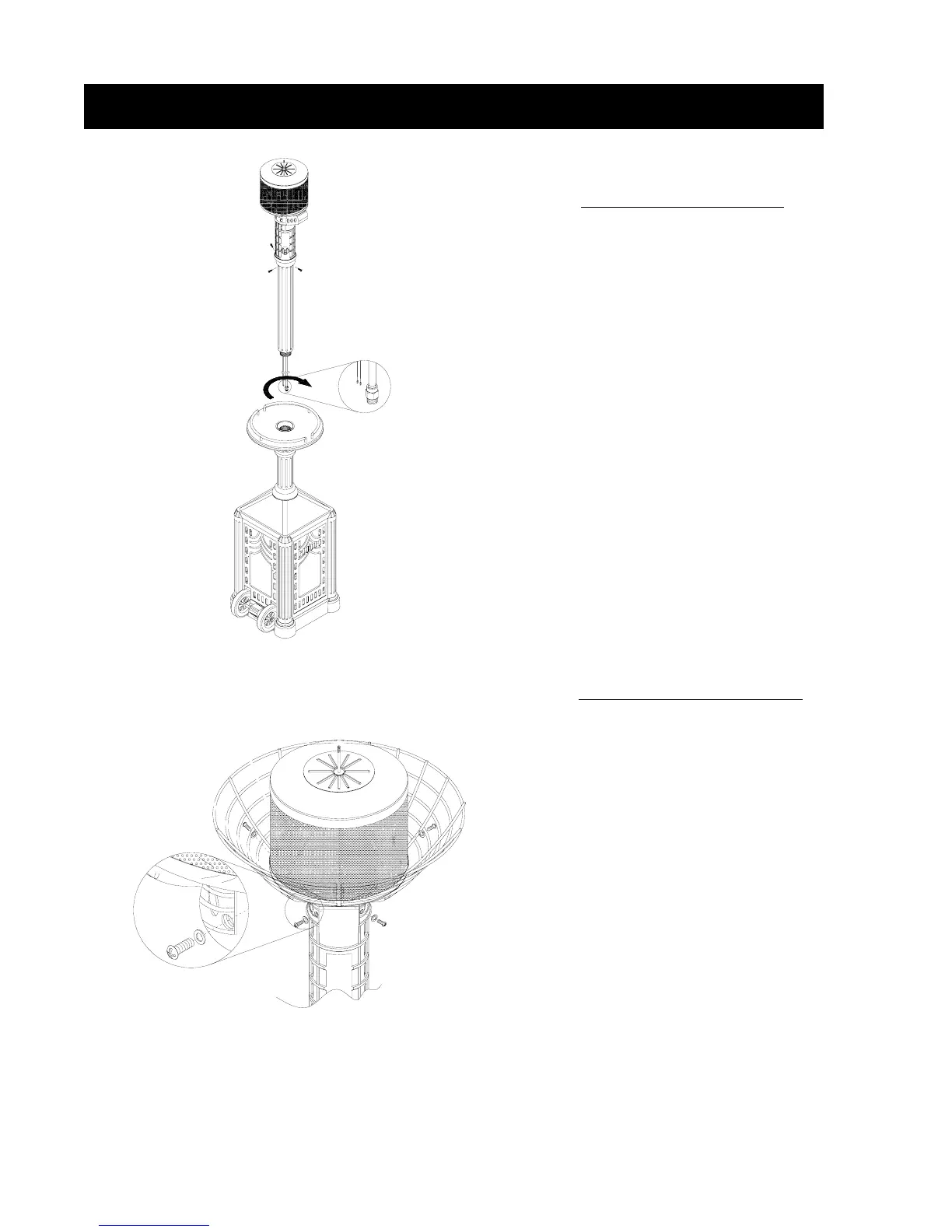
STEP 5. Heater Body Assembly
● Put the Post into the hole of
Granite Table. Please make sure that
the Gas Hose End and two Wires go
through the hole and can be reached
from the interior of the Base Housing.
● Turn the Post clockwise until it
is tightly secured.
● Turn the head assembly to align
the Control Panel to the same side as
the Door of the Base Housing.
Secure the Heater Body with 3pcs 1/4”
x 25mm Flat Head Screws as shown
in the diagram to the left.
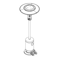
STEP 6. Emitter Screen Assembly
● The Emitter Screen comes as two
pieces which fit together just under the
base of the Emitter Screen. Needed for
this step are 4 - 1/4” x 20mm Truss
Head Screws and 4 - 1/4” Flat Washers.
● Align the open area at the bottom of
the Emitter Screen with the four holes in
the Control Panel Housing and using the
4 screws with washers installed on the
screws attach the Emitter Screen to the
Control Panel Housing as shown in the
diagram to the left.
7