GEO M12 HARDWARE SETUP PROCEDURE Page 51/90
IMPORTANT
Motor hoist must be rated to support entire cluster weight. Please check configuration
in NS-1 for proper motor hoist rating
Procedure
GEO M12 Left
- Position first GEO M12 so that Autorig
TM
is at the bottom
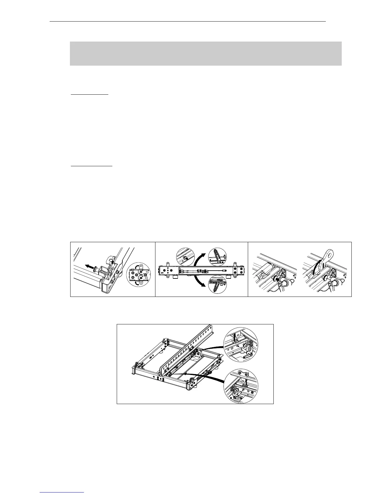
- Pull the bumper front latches, rotate the lower links so that connection points are double leg and
release the latches.
- Position bumper on top of first GEO M12 and lock front points to the bumper with 2 BL820 quick
release pins.
- Connect the bumper link bar (0° / “S" position) to GEO M12 rear rigging plate (hole marked “bumper”)
Lock with the quick release pin BL0825.
GEO M12 Right
- Position first GEO M12 so that Autorig
TM
is at the top and set in automatic lock position
- Pull the bumper front latches, rotate the lower links so that connection points are single leg and
release the latches.
- Position bumper on top of first GEO M12, front points will lock automatically
- Connect the bumper link bar (0° / “S" position) to GEO M12 rear rigging plate (hole marked “bumper”).
Lock with the quick release pin BL0825.
- If flying with bumper only, pull front and rear center latches, and release front and rear bumper
connecting points.
- If required, position VNT-EXBARM12 frontwards or rearwards into VNT-BUMPM12 slots and lock
devices with the quick release pins 12x40 stored on VNT-BUMPM12.
 Loading...