Page 52/90 GEO M12 HARDWARE SETUP PROCEDURE
o If using 1 hoist on VNT-EXBARM12, holes are “A” to “T”
o If using 2 hoists on VNT-EXBARM12, connect these using extreme holes (“A” and “T”)
o VNT-BUMPM12 without extension bar can only be flown with 2 hoists from front and rear
rigging points
- Connect hoist hook(s) to shackle(s) and lift assembly to sufficient height in order to connect a second
GEO M12
IMPORTANT
Ensure hoist hook(s) is (are) properly secured to VNT-BUMPM12 or VNT-EXBARM12
shackle(s)
Ensure that all quick release pins are locked
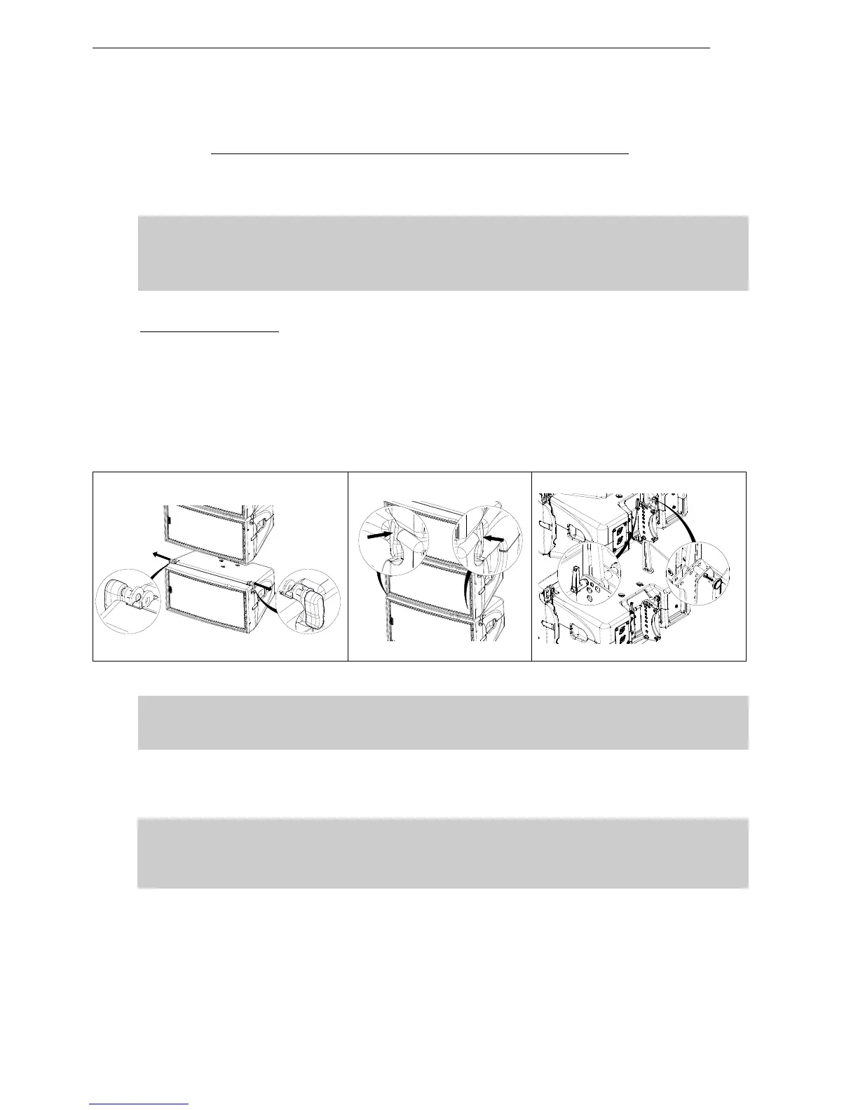
Subsequent GEO M12s
- Position second GEO M12 cabinet with AutoRig
TM
in automatic lock position, and lock front points to
first GEO M12
- Unlock GEO M12 link bar
- Pull the latch to engage the guide in GEO M12 rear slot.
- Adjust the angle by inserting quick release pin BL820 in proper hole.
- Connect subsequent GEO M12 cabinets as with second.
IMPORTANT
Ensure that bumper quick release pins are properly locked into GEO M12, and that all
AutoRig
TM
and rear connecting points are locked
- Lift cluster to NS-1 defined rigging height, secure cluster horizontally to prevent it from rotating;
- Secure bumper with secondary safety steel.
IMPORTANT
The requirements for secondary safety systems vary with territories. However, the
secondary safety steel MUST have a SWL equivalent or greater than that of the rigging
system.
 Loading...